3
\$\begingroup\$

I think I understand how the astable multivibrator works once the LEDs are blinking (cf. below), but I don't understand how the first cycle begins.
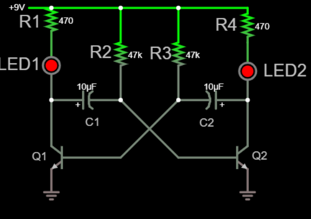
enter image description here
I can see that at first, the 2 LEDs are on (based on this simulation) so it's means that Q1 base and Q2 base are high. Also C1 is charging via R2 and C2 is charging via R3.

Then suddenly, the voltage across one of the capacitor reverses its direction (in the simulation linked it's around 370ms). I don't understand why this is happening. Why the capacitors do not continue to charge or stay fully charged ? Why the current flowing through one of them reverse its direction?

All the articles and questions/answers I read start after this step and miss this crucial explanation (cf. this answer "Assume that transistor Q1 has just switched “OFF”")


If I understood well, this is how the cycles work:

When LED 1 is turned on, it's because of a high voltage on Q1 base (and the left side of C2). While LED1 is on, C1 is charging via R2 until its right side reach a high enough voltage to switch on Q2 (via its base). This switches on LED2 and discharge C2 via Q2 thus lowering the voltage on Q1 base which turn off LED1. Now C2 is charging via R3 until its left side reaches a high enough voltage to switch on Q1 base which switches LED1 on. Then the cycle continues.

\$\endgroup\$
1
  • \$\begingroup\$ "All the articles and questions/answers I read start after this step and miss this crucial explanation" - Totally! One of those circuits in which textbooks silently ignore "ideal" components for the sake of explanation .. \$\endgroup\$
    – Mitu Raj
    Commented Nov 29, 2020 at 0:56

1 Answer 1

8
\$\begingroup\$

First, at some point the power must be turned from on to off.

Second, in the real circuit the capacitors won't be exactly 10.000 uF (or exactly equal to each other) and the collector resistors won't be exactly 47.000 kohms (or exactly equal to each other). (And the BJT's won't have exactly the same \$\beta\$ and the LEDs won't have exactly the same forward voltage, etc.)

The imbalance between the component values on the two sides at start up will produce a slight difference in which BJT gets turned on first, starting the oscillation.

To see the start-up behavior in the simulator, you will have to tune one of the circuit parameters slightly off (maybe 1 or 2%) and simulate the transient when the power supply is ramped up from 0 to 9 V.

\$\endgroup\$
9
  • \$\begingroup\$ It's possible that if you're unlucky enough to get well-matched components in such a circuit it will get "stuck" when you turn it on, and stay that way, because with the transistors saturated they can never kick themselves out of the both-LED-on state. It's not a concern for hobbyist or student circuits. For production, however, prudent designers would add some biasing to the transistors so that they're not fully saturated -- then circuit noise could kick the thing one way or another on start-up. \$\endgroup\$
    – TimWescott
    Commented Nov 28, 2020 at 20:28
  • \$\begingroup\$ Thanks @thePhoton for this. So does this means that when the power is turned on both, no LED and no BJT are turned on and both of the capacitors start charging. Then one of the capacitor (lets say C1) charges a bit faster reaching the 0.7V needed to turn on the Q2, which turns on LED2 and allows C2 to charge faster than C1, thus turning Q1 on which starts the cycles. If this is right, the simulation is misleading and in a real circuit, both LEDs are never turned on at the same time even during the first millisecond after the power is turned on. Is this right? \$\endgroup\$
    – MagTun
    Commented Nov 28, 2020 at 20:49
  • \$\begingroup\$ @TimWescott, I received your comment right after writing my comment... So now I am really confused because what you imply is that the simulation can actually be correct by turning on both LED at the same time. But then you say that a real circuit will get stuck in this both-LED-on state but the simulation is "able" to get out of this state somehow around 370ms. Is this a mistake from the simulation? I don't understand how the simulation does this and this is why I ask this question here. Thanks for your help! \$\endgroup\$
    – MagTun
    Commented Nov 28, 2020 at 20:56
  • \$\begingroup\$ @MagTun only in very rare circumstances will this happen in real life. It takes really well matched components, and a power supply rail that comes up slowly. And in the real world, if you wanted alternately blinking lights you'd at least use a 555 timer and a transistor or two, not this circuit. So my comment is really just for academic interest, not for real design. \$\endgroup\$
    – TimWescott
    Commented Nov 28, 2020 at 21:21
  • \$\begingroup\$ @TimWescott Even with perfectly matched components, the circuit would still start up simply due to noise, caused by such things as Brownian motion, quantum effects, possibly even stray external magnetic or electric fields. \$\endgroup\$ Commented Nov 29, 2020 at 4:23

Your Answer

By clicking “Post Your Answer”, you agree to our terms of service and acknowledge you have read our privacy policy.

Not the answer you're looking for? Browse other questions tagged or ask your own question.