6
\$\begingroup\$

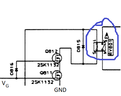
background first: I am currently trying to repair my old Pioneer amplifier (A-405R). The error description behaviour is a sporadic infinite triggering of the relay (marked blue one in the schematics). In the working case, V_G = 4.8 V. In the not working case it is below 4 V.

What I am really wondering (due to lack of HW experience): Why are these two MOSFETs (2SK1132: Datasheet MOSFET) in series? So I thought the benefit of that MOSFET is to switch the relay on and off. Why do you need to then there?

Detailed MOSFET schematic

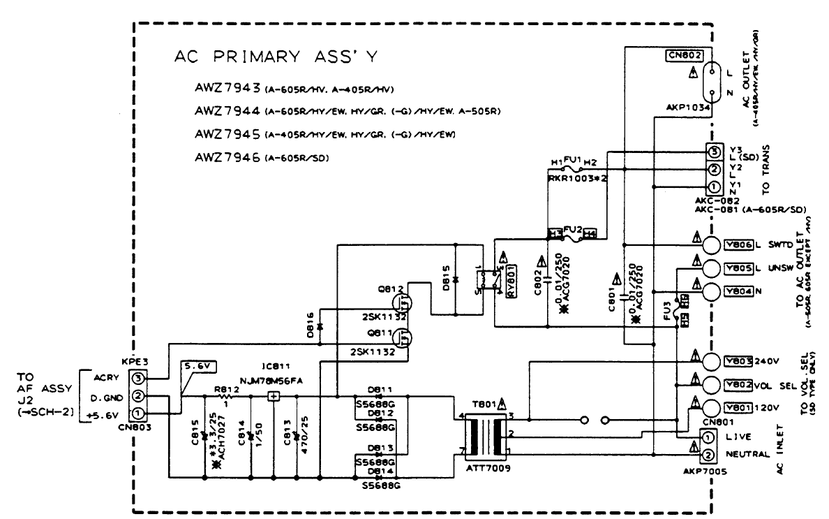
EDIT: See here for the more detailed schematic. Complete datasheet of the amplifier can be found under: Datasheet Amplifier

Primary Assy / Power Supply

\$\endgroup\$
12
  • \$\begingroup\$ It does look odd - the MOSFETs have an in-built gate-source resistor too - another odd-ball thing to have. Are you absolutely positive that GND connects where you show it? \$\endgroup\$
    – Andy aka
    Commented Dec 3, 2020 at 17:14
  • \$\begingroup\$ @Andyaka what "resistor"? There's some sort of bidirectional breakdown diode thing between gate and source on the data sheet, likely an early form of ESD protection as unprotected gates of early FET's were notorious for ESD damage in handling. \$\endgroup\$ Commented Dec 3, 2020 at 17:27
  • \$\begingroup\$ Look at the first page bullets @ChrisStratton - I don't know if this constitutes an inbuilt resistor but it sounds like one and the circuit would need it. \$\endgroup\$
    – Andy aka
    Commented Dec 3, 2020 at 17:30
  • \$\begingroup\$ One strategy, at least if the surrounding circuitry can be sufficiently understood to validate it, might be to use a single more robust modern logic-level FET... \$\endgroup\$ Commented Dec 3, 2020 at 17:30
  • \$\begingroup\$ @Andyaka "can be replaced with any resistor self-contained type transistor" is a Japanese to English mistranslation of what replaces what, to quote the NEC application guide for these "in applications, such as interfacing small signals, where the MOS FET is used in a low current region, the MOS FET can smoothly replace the existing transistors containing resistors." datasheetarchive.com/pdf/… The gate protection diode thingy is also mentioned. \$\endgroup\$ Commented Dec 3, 2020 at 17:43

1 Answer 1

1
\$\begingroup\$

The problem with MOSFET especially in power circuits and noisy environments is 'Single Event Upset' (SEU) that creates a 'Single Event Latch-up' (SEL). The SEU can make a MOSFET to turn on un-intentionally and in the case of SEL, the MOSFET won't turn off anymore until we recycle the power line. The use of two MOSFETs in series makes it possible to lower the probability of these events. If one of the MOSFETs is turned on by an SEL, the other one will prevent the current pass. More info can be found here:

Wikipedia - Latch-up

\$\endgroup\$

Your Answer

By clicking “Post Your Answer”, you agree to our terms of service and acknowledge you have read our privacy policy.

Not the answer you're looking for? Browse other questions tagged or ask your own question.