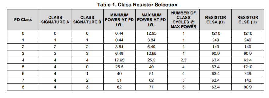
- Why does there seem to be a minimum power for certain class (e.g. PD class 2, 3.84W - 6.49W min to max)? What if the PD device idles down and is using a low 0.5W power? What would happen then? Must I design to ensure that it doesn't go below that?
I'm not sure exactly what the "minimum power" in that table means, but the "maximum power" column looks like it's indicating the maximum power than the PD can expect to receive for a given classification after accounting for cable losses. For example, for class 8 the PSE will deliver up to 90 W but the PD can only expect to receive 71 W after accounting for cable losses.
In any case, section 7.4.8 "Maintain Power Signature" of the linked datasheet describes the minimum load the PD must provide in order to ensure that the PSE does not disconnect. That section describes the requirements of the PoE standard as well as the controls you have for that particular PD chip to program the MPS current pulses that the chip generates for you (AMPS_CTL and MPS_DUTY pins).
- What would happen if the PSE can't deliver the power requirement of the PD device, so the PD device is on a higher classification than what the PSE can deliver. Would power still be given to the PD device but only the highest it can go? Where does the responsibility of protecting both equipment from damage due to lack of power? Is it the job of the PoE PD controller to outright not give power, or its further down the line where the PoE PD controller send a signal to the microcontroller/processor that not enough power is available (designer's responsibility), or simply the PSE will just straight up not give power?
The PD determines the maximum power capabilities of the PSE by the number of class events the PSE uses (and the duration of the first class event). This particular PD chip then outputs the PSE Type on its TPL, TPH, and BT pins. See section 7.3.5 and in particular Table 3, which deals with power demotion cases in which the PSE cannot supply as much power as the PD is requesting.
The PD's TPL, TPH, and BT pins provide you with the information you need to determine how much power the PD is allocated by the PSE so that you can prevent the power drawn by the PD and its load from exceeding that allocated power. The PD does have a current limit, but this is designed protect against a short circuit -- it allows up to the maximum power that the maximum classification supported by the PD allows (i.e. it isn't based on the classification the PD is requesting nor on the power allocated by the PSE). The PSE also provides protection if too much power is drawn -- e.g. TI's TPS23881 PSE, which is a Type 4 PSE designed to work with the TPS2372 PD you are looking at, has its own current limiting as well as classification-based power limiting ("port power policing").

