2
\$\begingroup\$

I've been doing an experiment which involves measuring the voltage across the capacitor at different driving frequencies. Consider the circuit below: enter image description here

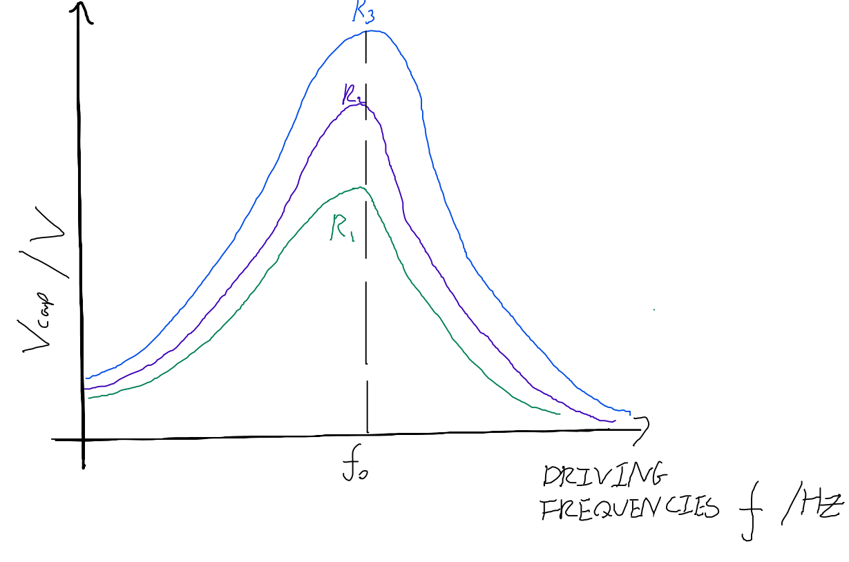
A sketch of the experimental curve \$(R_1<R_2<R_3)\$ with $(L,C)$ constant:enter image description here

However I am still trying to understand why resonance takes place in the first place. My logic is as follows:

\$V_L\$ and \$V_C\$ are in antiphase with each other (the inductor is in phase with the capacitor), so the voltage of the LC combination and hence the voltage of the circuit is: $$V=V_L-V_C$$ \$V\$ is in phase with \$I_R\$. The circuit current is $$I=\sqrt{I_{LC}^2+I_R^2}$$ $$\frac{V}{Z}=\sqrt{\left(\frac{V}{Z_{LC}}\right)^2+\left(\frac{V}{R}\right)^2}$$. Since \$V=V_{LC}=V_L-V-C\$, \$I_{LC}Z_{LC}=I_{LC}X_L-I_{LC}X_C\$, $$Z_{LC}=X_L-X_{C}$$ $$\frac{1}{Z}=\sqrt{\frac{1}{(X_L-X_C)^2}+\frac{1}{R^2}} \to Z=\frac{|X_L-X_R|R}{R^2+(X_L-X_C)^2}$$ For resonance, \$X_L=X_C \to Z=0\$. But \$Z=0\$ would lead to \$I \to \infty \$ so something isn't right with my derivation for \$Z\$ (circuit impedence)?

Also, I have been given the amplitude of the resonance peak: $$A=\frac{k}{\sqrt{(\omega^2-\omega_0^2)^2+(\gamma \omega)^2}}$$ where \$k\$ is some normalisation factor, \$\omega=2\pi f\$ and \$\gamma\$ is the damping coefficient. For \$A\$ to increase with \$R\$, am I correct to assume that \$\gamma \propto \frac{1}{R}\$? Is there a differential equation to describe the circuit?

EDIT: The internal reactance of the voltage source ~\$ 600 \Omega \$, \$(R_1,R_2,R_3)=(1\Omega, 2\Omega, 3\Omega)\$, /$L=1mH, C=100nF$/ I obtained the folliwing differential eq.: $$\ddot{I}_{LC}(t)+\frac{1}{L}\frac{R_{output}R}{R+R_{output}}\dot{I}_{LC(t)}+\frac{I_{LC}(t)}{LC}=\frac{RV_0 \omega cos(\omega t)}{(R+R_{output})L}$$, where \$\omega\$ is the driving angular frequency and \$V_0\$ is the peak driving voltage. This means \$\gamma=\frac{R_{output}R}{L(R+R_{output})}\$ even if the output resistance is taken into account, but wouldn't higher R lead to higher \$\gamma\$ and hence lower amplitude?

\$\endgroup\$
6
  • 3
    \$\begingroup\$ Is your voltage source ideal or does it have an internal resistance not shown in your diagram? \$\endgroup\$
    – The Photon
    Commented Dec 6, 2020 at 0:42
  • \$\begingroup\$ Put your question right please. As you currently have it "R" will have no effect whatsoever let alone R1, R2 and R3 (wherever they may be). \$\endgroup\$
    – Andy aka
    Commented Dec 6, 2020 at 10:54
  • \$\begingroup\$ I just figured out that the voltage source (picoscope) has an internal reactance of \$600 \Omega \$ (\$ R_1,R_2,R_3)=1\Omega, 2\Omega, 3\Omega\$? \$\endgroup\$ Commented Dec 6, 2020 at 10:56
  • \$\begingroup\$ Please see edits, I obtained a differential eq. but it makes no sense. \$\endgroup\$ Commented Dec 6, 2020 at 14:20
  • \$\begingroup\$ @floccinaucinihilipilificator What are your values for \$L\$ and \$C\$? \$\endgroup\$ Commented Dec 6, 2020 at 14:41

2 Answers 2

2
\$\begingroup\$

The equivalent impedance you calculated is only valid if you measure it across \$R\$, disregarding the source, but your output is across \$C\$. To calculate the transfer function first you must account for the impedance (let's consider it a resistance) of the voltage source, which can be modelled as a series resistance. It doesn't make sense otherwise, since a voltage source is considered zero, or very low impedance, thus a resistor across it which is larger that its source will not contribute with anything.

Consider the voltage across \$R\$ to be \$V_1\$. Then, the impedance seen from the source's side is \$Z_1\$:

$$\begin{align*} Z_{LC}&=sL+\dfrac{1}{sC}\tag{1} \\ Z_1&=\dfrac{1}{\dfrac{1}{Z_{LC}}+\dfrac{1}{R}} \\ &=R\dfrac{s^2+\dfrac{1}{LC}}{s^2+\dfrac{R}{L}s+\dfrac{1}{LC}}\tag{2} \\ &\Rightarrow \\ V_{out}&=V_1\dfrac{Z_1}{Z_1+R_{in}}\tag{3} \\ &\Rightarrow \\ H(s)&=\dfrac{R}{R_{in}+R}\dfrac{s^2+\dfrac{1}{LC}}{s^2+\dfrac{R_{in}}{R_{in}+R}\dfrac{R}{L}s+\dfrac{1}{LC}}\tag{4} \end{align*}$$

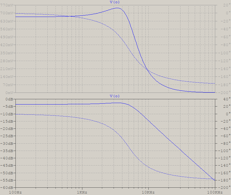
\$(4)\$ shows an attenuated and damped 2nd order lowpass, which should have a response something like this (for some random values of \$L=1\;\text{mH},\;C=1\;\mu\text{F},\;R=100\;\Omega,\;R_{in}=50\;\Omega\$):

test

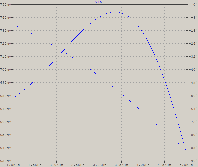
But your plots show only a peak resembling a bandpass. So, in the event that your connections are according to your schematic, I would guess that you're only measuring a finite bandwidth around the peak, something like this:

range

If this is the case, then you need to increase the range, otherwise it's possible you have something different, and it can only be determined by showing the actual values for the elements (including parasitics, for L, at least), source's output impedance, point of measuring, how it's measured, range of frequencies and amplitudes/magnitudes you're measuring.


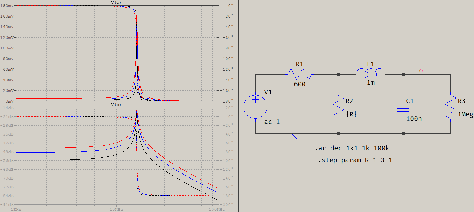
Given the recent edit, you still haven't said what is the range of frequencies you're mesuring, but here is the reworked response of your circuit with your values:

new

This further reinforces my guess that you're measuring the output over a limited bandwidth, creating the illusion that it's a bandpass, instead of a very underdamped lowpass.

As for the damping, as your newly found formula shows, it's exactly as shown in my derivation, which means that the usual \$R/L\$ is now \$R_{eq}/L\$, where \$R_{eq}=R_{in}||R\$. In short, both \$R\$ and \$R_{in}\$ contribute. And if \$L\$ had a series resistance, that would have been in there, too. If it makes it easier for you, here's the rewritten transfer function:

$$H(s)=\dfrac{R}{R_{in}+R}\dfrac{s^2+\dfrac{1}{LC}}{s^2+\dfrac{R_{in}||R}{L}s+\dfrac{1}{LC}}$$

\$\endgroup\$
1
  • 1
    \$\begingroup\$ Your new edit seemed to make it more clear what your question is, see if the update helps. \$\endgroup\$ Commented Dec 6, 2020 at 15:42
1
\$\begingroup\$

First, I will present a method that uses Mathematica to solve this problem. When I was studying this stuff I used the method all the time (without using Mathematica of course). Besides that the answer of @a concerned citizen is excellent.

Well, we are trying to analyze the following circuit:
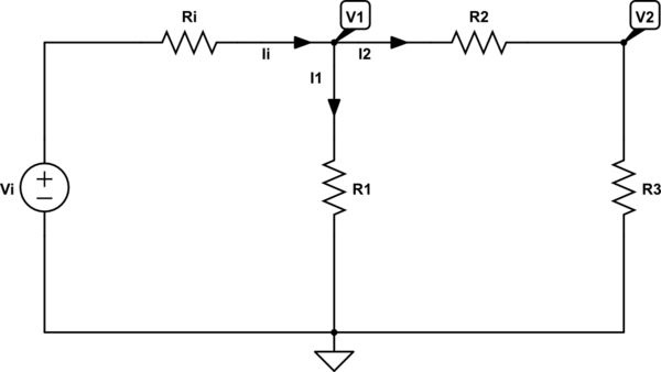
schematic

simulate this circuit – Schematic created using CircuitLab

When we use and apply KCL, we can write the following set of equations:

$$\text{I}_\text{i}=\text{I}_1+\text{I}_2\tag1$$

When we use and apply Ohm's law, we can write the following set of equations:

$$ \begin{cases} \text{I}_\text{i}=\frac{\text{V}_\text{i}-\text{V}_1}{\text{R}_1}\\ \\ \text{I}_1=\frac{\text{V}_1}{\text{R}_1}\\ \\ \text{I}_2=\frac{\text{V}_1-\text{V}_2}{\text{R}_2}\\ \\ \text{I}_2=\frac{\text{V}_2}{\text{R}_3} \end{cases}\tag2 $$

Substitute \$(2)\$ into \$(1)\$, in order to get:

$$ \begin{cases} \frac{\text{V}_\text{i}-\text{V}_1}{\text{R}_1}=\frac{\text{V}_1}{\text{R}_1}+\frac{\text{V}_1-\text{V}_2}{\text{R}_2}\\ \\ \frac{\text{V}_\text{i}-\text{V}_1}{\text{R}_1}=\frac{\text{V}_1}{\text{R}_1}+\frac{\text{V}_2}{\text{R}_3} \end{cases}\tag3 $$

Now, we can solve for \$\text{V}_2\$:

$$\text{V}_2=\frac{\text{R}_1\text{R}_3\text{V}_\text{i}}{\text{R}_\text{i}\left(\text{R}_2+\text{R}_3\right)+\text{R}_1\left(\text{R}_\text{i}+\text{R}_2+\text{R}_3\right)}\tag4$$

Where I used the following Mathematica-code to find \$(4)\$:

In[1]:=FullSimplify[
 Solve[{Ii == I1 + I2, Ii == (Vi - V1)/Ri, I1 == V1/R1, 
   I2 == (V1 - V2)/R2, I2 == V2/R3}, {Ii, I1, I2, V1, V2}]]

Out[1]={{Ii -> ((R1 + R2 + R3) Vi)/((R2 + R3) Ri + R1 (R2 + R3 + Ri)), 
  I1 -> ((R2 + R3) Vi)/((R2 + R3) Ri + R1 (R2 + R3 + Ri)), 
  I2 -> (R1 Vi)/((R2 + R3) Ri + R1 (R2 + R3 + Ri)), 
  V1 -> (R1 (R2 + R3) Vi)/((R2 + R3) Ri + R1 (R2 + R3 + Ri)), 
  V2 -> (R1 R3 Vi)/((R2 + R3) Ri + R1 (R2 + R3 + Ri))}}

So, the transfer function is given by:

$$\mathcal{H}:=\frac{\text{V}_2}{\text{V}_\text{i}}=\frac{\text{R}_1\text{R}_3}{\text{R}_\text{i}\left(\text{R}_2+\text{R}_3\right)+\text{R}_1\left(\text{R}_\text{i}+\text{R}_2+\text{R}_3\right)}\tag5$$


Now, applying this to your circuit we need to use (from now on I use the lower case letters for the function in the 'complex' s-domain where I used Laplace transform):

  • $$\text{R}_2=\text{sL}\tag6$$
  • $$\text{R}_3=\frac{1}{\text{sC}}\tag7$$

So, we can rewrite \$(5)\$:

$$\mathcal{h}\left(\text{s}\right)=\frac{\text{R}_1\cdot\frac{1}{\text{sC}}}{\text{R}_\text{i}\left(\text{sL}+\frac{1}{\text{sC}}\right)+\text{R}_1\left(\text{R}_\text{i}+\text{sL}+\frac{1}{\text{sC}}\right)}=$$ $$\frac{\text{R}_1}{\text{CL}\left(\text{R}_\text{i}+\text{R}_1\right)\text{s}^2+\text{CR}_\text{i}\text{R}_1\text{s}+\text{R}_\text{i}+\text{R}_1}\tag8$$

Using the fact that for sinusoidal voltages we know that \$\text{s}:=\text{j}\omega\$ (where \$\text{j}^2=-1\$ and \$\omega=2\pi\text{f}\$), we can write for the amplitude:

$$\left|\underline{\mathcal{h}}\left(\text{j}\omega\right)\right|=\left|\frac{\text{R}_1}{\text{CL}\left(\text{R}_\text{i}+\text{R}_1\right)\left(\text{j}\omega\right)^2+\text{CR}_\text{i}\text{R}_1\text{j}\omega+\text{R}_\text{i}+\text{R}_1}\right|=$$ $$\frac{\left|\text{R}_1\right|}{\left|\text{R}_\text{i}+\text{R}_1-\text{CL}\left(\text{R}_\text{i}+\text{R}_1\right)\omega^2+\text{CR}_\text{i}\text{R}_1\omega\text{j}\right|}=$$ $$\frac{\text{R}_1}{\sqrt{\left(\text{R}_\text{i}+\text{R}_1-\text{CL}\left(\text{R}_\text{i}+\text{R}_1\right)\omega^2\right)^2+\left(\text{CR}_\text{i}\text{R}_1\omega\right)^2}}\tag9$$

Now, using the fact that \$\text{R}_\text{i}=600\space\Omega\$, \$\text{C}=100\cdot10^{-9}\space\text{F}\$, and \$\text{L}=1\cdot10^{-3}\space\text{H}\$. So we get:

$$\displaystyle\left|\underline{\mathcal{h}}\left(\text{j}\omega\right)\right|=\frac{10^{10}\text{R}_1}{\sqrt{\left(\text{R}_1+600\right)^2\omega^4+2\cdot10^{10}\left(\text{R}_1\left(17\text{R}_1-1200\right)-360000\right)\omega^2+10^{20}\left(\text{R}_1+600\right)^2}}\tag{10}$$

Where I used the following Mathematica-code to find \$(10)\$:

In[2]:=Clear["Global`*"];
x = R1/(R1 + Ri + c R1 Ri s + c L (R1 + Ri) s^2);
s = I*\[Omega];
Ri = 600;
c = 100*10^(-9);
L = 1*10^(-3);
FullSimplify[
 Sqrt[(ComplexExpand[Re[x]])^2 + (ComplexExpand[Im[x]])^2], 
 Assumptions -> R1 > 0 && \[Omega] >= 0]

Out[2]=(10000000000 R1)/Sqrt[
100000000000000000000 (600 + R1)^2 + 
 20000000000 (-360000 + R1 (-1200 + 17 R1)) \[Omega]^2 + (600 + 
    R1)^2 \[Omega]^4]

The maximum occurs when (assuming that it must be positive):

$$\omega_0=2\pi\text{f}_0=\frac{100000\sqrt{\text{R}_1\left(1200-17\text{R}_1\right)+360000}}{\text{R}_1+600}\space\Longleftrightarrow\space$$ $$\text{f}_0=\frac{100000\sqrt{\text{R}_1\left(1200-17\text{R}_1\right)+360000}}{2\pi\left(\text{R}_1+600\right)}=\frac{50000\sqrt{\text{R}_1\left(1200-17\text{R}_1\right)+360000}}{\pi\left(\text{R}_1+600\right)}\tag{11}$$

Where I used the following Mathematica-code to find \$(11)\$:

In[3]:=FullSimplify[
 Solve[{D[%2, \[Omega]] == 0, R1 > 0 && \[Omega] >= 0}, \[Omega]]]

Out[3]={{\[Omega] -> 
   ConditionalExpression[0, 
    0 < R1 < 600/17 (1 + 3 Sqrt[2]) || 
     R1 > 600/17 (1 + 3 Sqrt[2])]}, {\[Omega] -> 
   ConditionalExpression[(100000 Sqrt[360000 + (1200 - 17 R1) R1])/(
    600 + R1), 0 < R1 < 600/17 (1 + 3 Sqrt[2])]}}
\$\endgroup\$

Your Answer

By clicking “Post Your Answer”, you agree to our terms of service and acknowledge you have read our privacy policy.

Not the answer you're looking for? Browse other questions tagged or ask your own question.