4
\$\begingroup\$

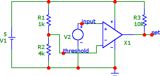
In this circuit we have a LM339 comparator which compares input signal with respect to the threshold value which is 4 volts.

lm339 comparator

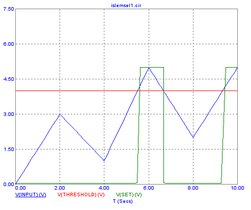
This is the output of the transient analysis.

lm339 transient analysis

If the input signal is above 4 volts, the comparator produces a logical "1" at the output.

Let's say we would like to make a battery charge controller circuit using this circuit.

If the battery voltage reaches upper threshold (4 volts in this case), we would like to cut off the charging voltage.

There might be many ways to achieve this but the first thing that comes to my mind was to use a circuit element with a memory.

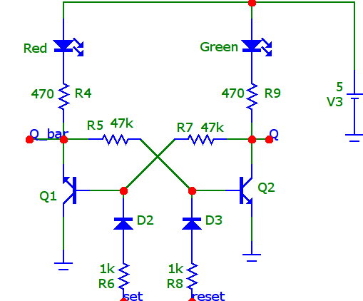
So, I decided to use this SR latch.

sr latch

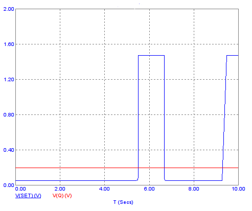
When I connect the output of comparator to the input of the SR latch I get this result.

comparator transient analysis

As you'd see from the transient analysis result. When we make set logical "1", Q output does not become logical "1"

Should I invert the set signal and give it to reset input?

Any ideas would be apreciated. Thanks.

Update :

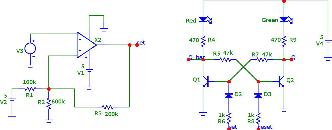
After reading the comments I've made some changes in the circuit. I used TLV301 instead of LM339. I've fixed the orientation of the Q1 transistor.

tlv301 comparator

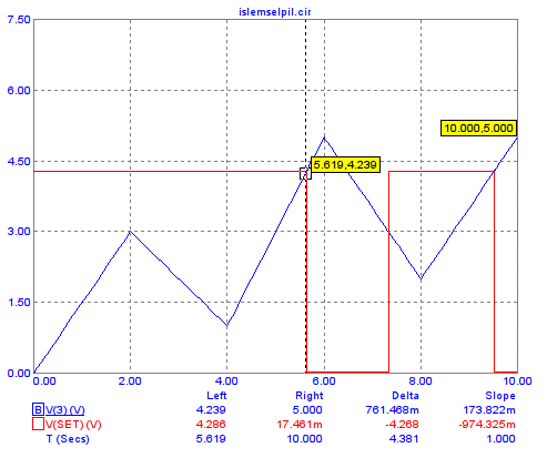
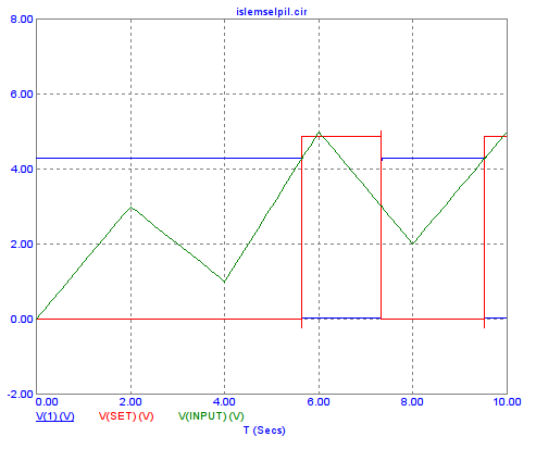
You may found the transient analysis results when set is not connected to BJT circuit.

If the input voltage is over 4.2 volts comparator produces logical "0" and if it is under 3 volts it produces logical "1" again.

tlv301 transient analysis

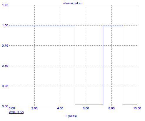
If I connect comparators set output to the input of the SR latch I get this result. As you'd see output of comparator scaled to about 1 volts.

set

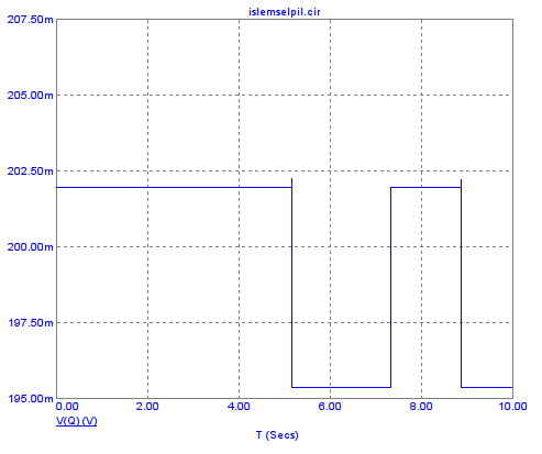
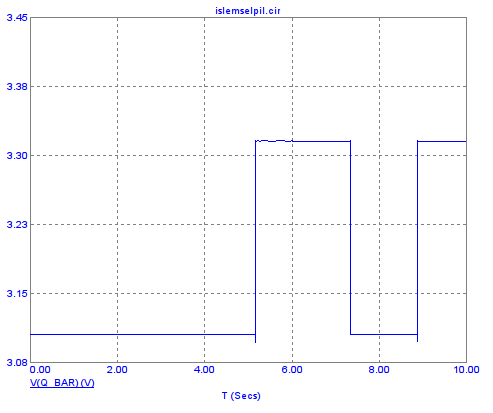
These are the Q and Q_bar output of the SR latch.

Q output Q bar output

\$\endgroup\$
8
  • 1
    \$\begingroup\$ Q1 is upside down. Rinse and repeat. Congrats on using a sensible simulator (microcap) and you can use digital SR latches mixed with analogue circuits in microcap. You might also want to use a much lower current comparator than the LM339 for monitoring battery voltages too. \$\endgroup\$
    – Andy aka
    Commented Dec 9, 2020 at 13:11
  • 1
    \$\begingroup\$ Much lower current comparator circuit. \$\endgroup\$
    – Andy aka
    Commented Dec 9, 2020 at 13:27
  • 4
    \$\begingroup\$ So, you have a set voltage of 4 volts. What is your reset voltage? If you know both, you can provide everything you need in a single comparator with positive feedback. It's called a Schmitt Trigger. \$\endgroup\$ Commented Dec 9, 2020 at 14:00
  • \$\begingroup\$ Thanks. I suppose I've understood what you've meant. Let's assume this was a lipo battery. Then set voltage would be 4.2 volts, and reset voltage would be 3.6 volts. \$\endgroup\$
    – user211748
    Commented Dec 9, 2020 at 14:14
  • 1
    \$\begingroup\$ These two application notes describe how to set hysteresis on a comparator to arrive at two tripping points: ti.com/lit/ug/tidu020a/tidu020a.pdf and maximintegrated.com/en/design/technical-documents/app-notes/3/…. This one may also interest you: maximintegrated.com/en/design/technical-documents/app-notes/6/… \$\endgroup\$
    – ocrdu
    Commented Dec 9, 2020 at 15:11

2 Answers 2

2
\$\begingroup\$

Well, you have a patchwork of different specifications for your hysteresis points: for high voltage, you asked for 4.2, your design actually yields 4.5 and you also mention 4.0. For low voltage, you asked for 3.6 and your design actually yields 3.0.

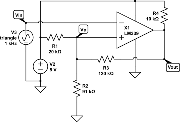
Let's assume that your thresholds in the comments - 4.2V and 3.6V - are the ones you actually want to use. You can drop the latch entirely since your Schmitt trigger itself is stateful. Then, your circuit can be (within E24 approximation)

schematic

simulate this circuit – Schematic created using CircuitLab

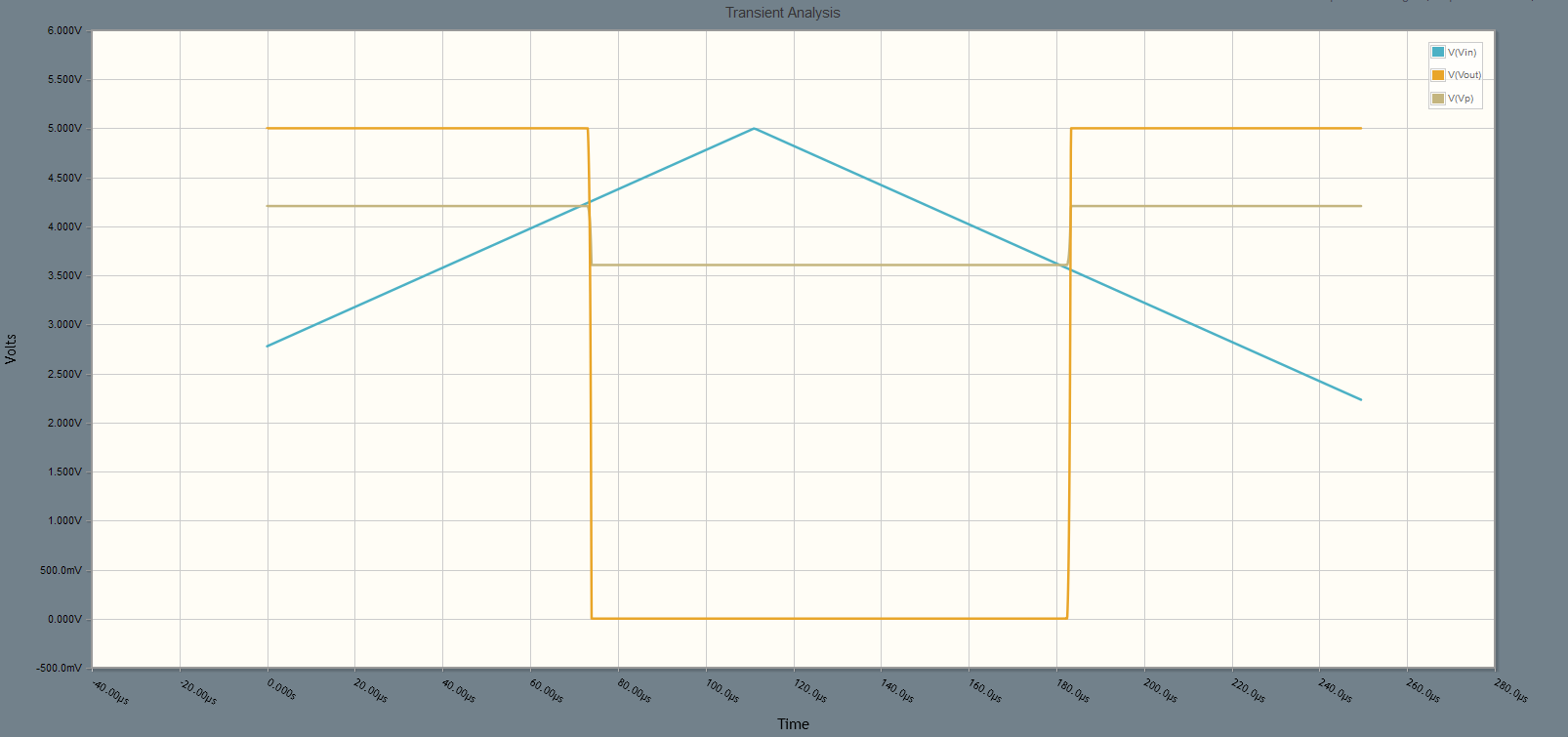
So far as I can tell, this matches what you expect from your battery sensor:

sim

\$\endgroup\$
3
  • 1
    \$\begingroup\$ Minor remark: The LM339 output is open-collector, so it needs a pull-up. \$\endgroup\$
    – ocrdu
    Commented Dec 10, 2020 at 19:11
  • \$\begingroup\$ @ocrdu Fair point; I'd forgotten that this was targeting a specific comparator. Edited. \$\endgroup\$
    – Reinderien
    Commented Dec 10, 2020 at 19:14
  • \$\begingroup\$ As you've noticed I used 4.5 volts for upper threshold voltage and 3 volts for lower threshold voltage in calculations. If you may look at the last picture in my answer, switching occurs at 4.2 volts. Therefore, I calculated the upper threshold as 0.3 volts higher in calculations. Thanks for the detailed answer. \$\endgroup\$
    – user211748
    Commented Dec 10, 2020 at 19:46
0
\$\begingroup\$

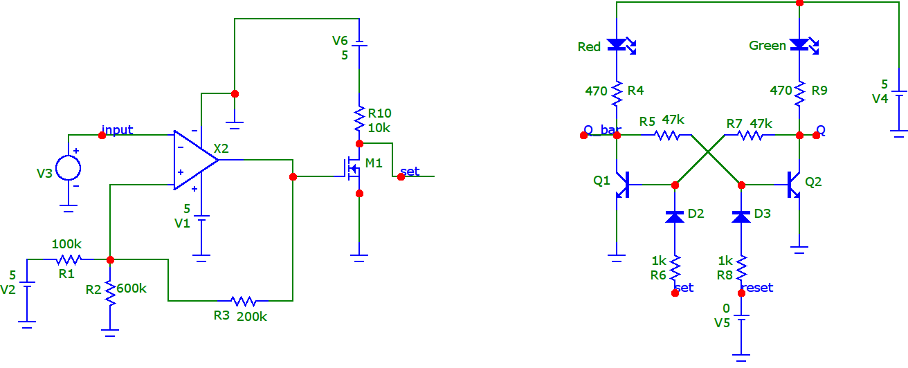
Adding a mosfet inverter at the output of comparator and connecting the input of reset pin to the ground seems to solve this problem.

tlv comparator

When the output of the comparator is not connected to S-R latch, the signals at the output of the comparator and mosfet is as follows:

tvl transient analysis

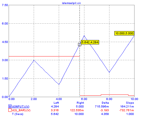
This transient analysis result shows the circuit after connecting set output of comparator to the input of S-R latch.

As you'd see whenever the input voltage is about 4.2 volts, the output of the Q_bar becomes 0.

tvl3

\$\endgroup\$

Your Answer

By clicking “Post Your Answer”, you agree to our terms of service and acknowledge you have read our privacy policy.