0
\$\begingroup\$

I have the ADS4249 differential ADC from Texas Instruments here is the datasheet. On page 55 it says:

For a full-scale differential input, each input pin (INP and INM) must swing symmetrically between VCM + 0.5 V and VCM – 0.5 V, resulting in a 2-VPP differential input swing

So I have a single ended signal that is converted to a differential one with an opamp (lets assume a gain of 1) and biased to VCM and fed into the INP and INM ports of the ADC. To get the full scale differential input my single ended signal has to swing between VCM-0.5V and VCM+0.5V. But my single ended signal never becomes negative. It swings from 0V to 0.5V.

How can it be done that I stil get the full-scale differential input on INP and INM?

If it swings from 0V to 1V will I get the full scale differential input?

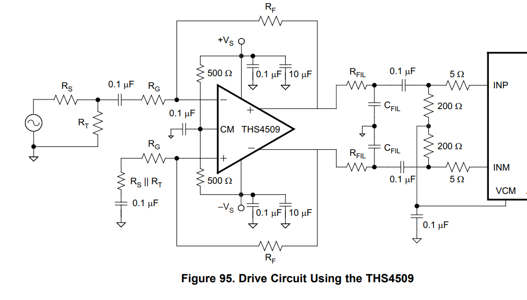
Here is the schematic: enter image description here

\$\endgroup\$
5
  • \$\begingroup\$ It doesn't make sense to use a differential ADC for acquiring a single ended signal. \$\endgroup\$ Commented Dec 9, 2020 at 15:13
  • \$\begingroup\$ @MarkoBuršič I don't have another choice \$\endgroup\$ Commented Dec 9, 2020 at 15:16
  • 1
    \$\begingroup\$ The opamp voltage range doesn't matter as long as it spans 1Vp-p. The AC coupling shown on the schematic will take care of correcting the common mode. \$\endgroup\$
    – user16324
    Commented Dec 9, 2020 at 15:36
  • \$\begingroup\$ Wouldn't be simpler to apply the Vcm to the THS4509, directly or through an opamp buffer? By the way you have accepted the answer too quick, now you won't get a true answer. \$\endgroup\$ Commented Dec 9, 2020 at 15:43
  • 1
    \$\begingroup\$ @BrianDrummond so to have a full scale diff. output it is enough when the voltage source swings between 0V and 1V? \$\endgroup\$ Commented Dec 9, 2020 at 16:31

1 Answer 1

2
\$\begingroup\$

This answer was made prior to the OP revealed that his inputs were AC coupled to the ADC hence, in the text below, it was presumed he was making a DC connection to the ADC: -

But my single ended signal never becomes negative; It swings from 0V to 0.5V.

Then, in comments: -

I have an opamp that centers it to 0.95V and outputs the differential signals with a gain of 1.

Given that it now is revealed to be an AC connection, there are no constraints on the mid-voltage-range of the preceding stage being centred at 2.5 volts, providing that series resistors are used to feed the ADC inputs in order to limit input current to levels that should be prescribed by the ADC data sheet.


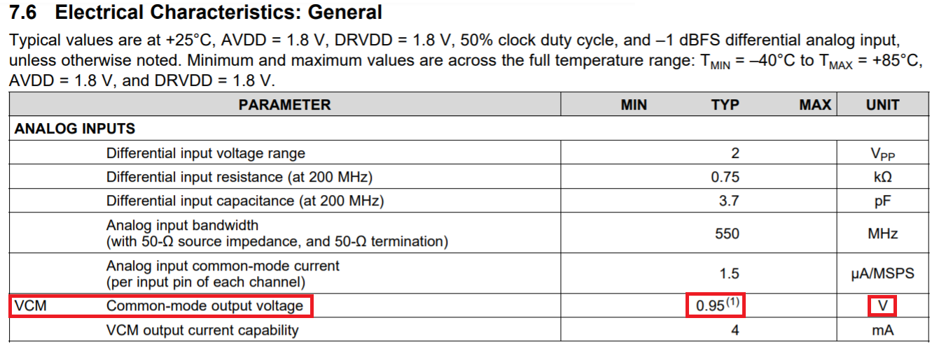
The ADS4249 has a VCM voltage of 0.95 volts: -

enter image description here

This means that for each input, the full scale signal needs to swing from +0.45 volts to +1.45 volts (a single-ended difference of 1 volt and an overall differential difference of 2 volts).

But my single ended signal never becomes negative. It swings from 0V to 0.5V.

OK, you need to adjust this so that it is centred on +0.95 volts and not +2.5 volts. Then, you need to reduce the maximum swings to that required by the ADC.

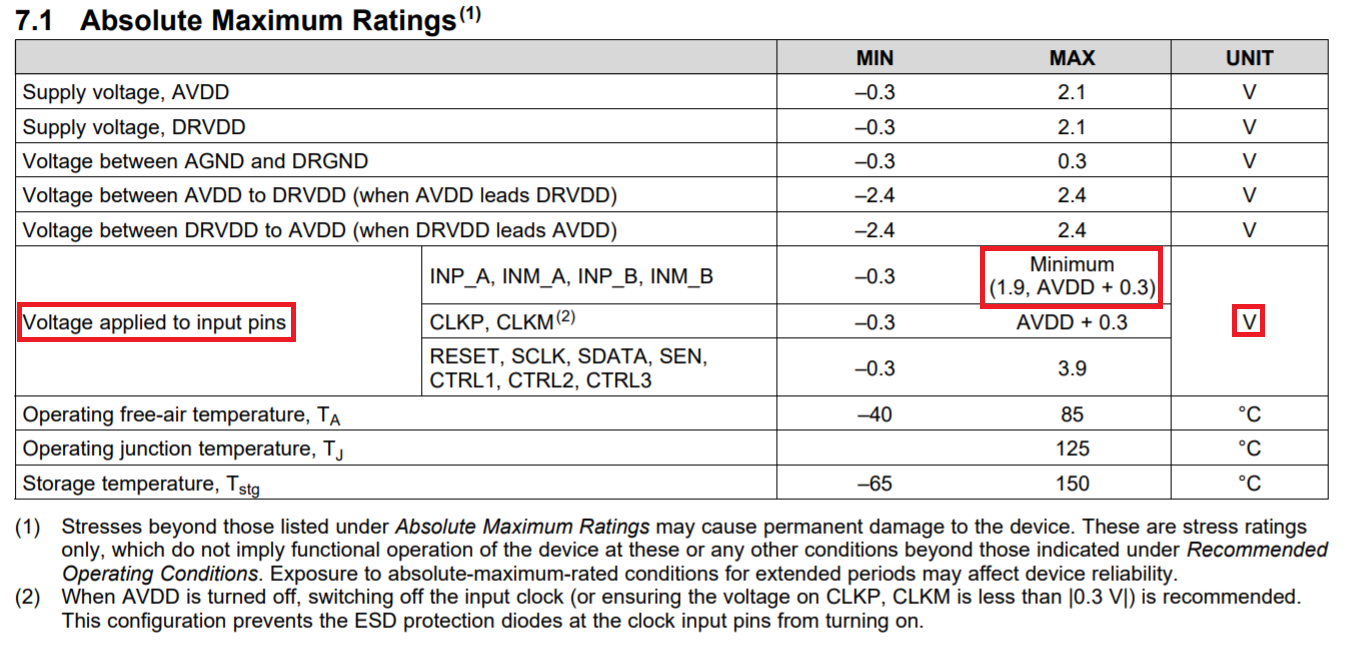
Resistors will be your friends here but make sure you observe this: -

enter image description here

\$\endgroup\$
2
  • \$\begingroup\$ Ok thank you. I have an opamp that centers it to 0.95V and outputs the differential signals with a gain of 1. If the opamps input signal swings from 0V to 0.5V, I will get only half of the full-scale signal? \$\endgroup\$ Commented Dec 9, 2020 at 15:15
  • \$\begingroup\$ The valid input pin voltage range is from +0.45 volts to +1.45 volts. \$\endgroup\$
    – Andy aka
    Commented Dec 9, 2020 at 15:20

Your Answer

By clicking “Post Your Answer”, you agree to our terms of service and acknowledge you have read our privacy policy.

Not the answer you're looking for? Browse other questions tagged or ask your own question.