9
\$\begingroup\$

I'm trying to connect a contact microphone to an Arduino.

I got a couple of LM833N audio dual opamps, which I'd like to put to use. I'm still struggling to understand opamps, though.

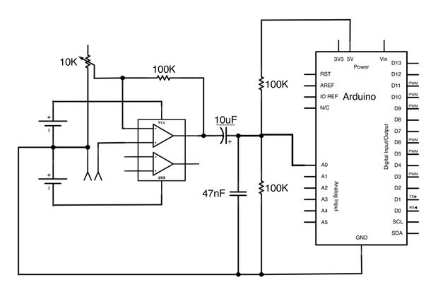
I've been reading an instructable on audio input on the Arduino. It uses the following circuit:

circuit diagram

(source: instructables.com)

However, this is for the TL072 opamp. I'm not really sure if I can use the LM833N in its place. Is this circuit suitable for a contact microphone?

Also, it would be great if someone could point me to a good (easy) introduction to opamps - the wikibooks page is a bit dense for me.

\$\endgroup\$

3 Answers 3

7
\$\begingroup\$

I know it's old, but may still interest someone. With a piezo contact mic, you may want to also connect two diodes allowing current to go from ground to mic output and from mic output to vcc. Under normal conditions there is not voltage over them, but a piezo can create some serious voltage spikes if hit, and this will protect your amp / arduino, so excess voltage can go to power supply rather than amp.

\$\endgroup\$
1
  • 1
    \$\begingroup\$ +1 for this essential circuit-saver: 20 volt spikes when tapping a piezo mic with a fingernail. \$\endgroup\$ Commented Jul 16, 2013 at 5:57
5
\$\begingroup\$

It will work, and Oli's suggestion of a capacitor is a good one. I'd point out a couple more things:

You don't have any capacitor to block any DC offset on the input. This is fine, if you are going directly to your microphone and you know there won't be any. However, if this is going to a connector on the box, you never know what people will plug in there, and it may work fine, until it doesn't, and your amplifier is fried. It's probably best to go for a non-polarized type here, since you don't know what people will plug into it.

Another issue: "Contact microphone" usually means a piezoelectric microphone. These are different from most other microphone types in that they have a very high output impedance, on the order of \$10M\Omega\$. The input impedance of your amplifier is an order of magnitude less, which will result in significant attenuation of the signal and alter the frequency response of the microphone-amplifier system. It will work, but it may not sound good. This is of course, subjective and depending on the timbre you desire.

The solution is buffering, converting a high impedance output into a low impedance output, or equivalently, amplifying the current. An op-amp can do this in a circuit called a voltage follower:

voltage follower schematic

Put this between your microphone and the input of the circuit you already have (on the microphone's side of the cable, if you can), and your amplifier's input impedance will be that of whatever op-amp you use, without otherwise changing the operation of your circuit. Oddly, I don't see an input impedance listed in the LM833N datasheet, but since it has a BJT input stage, it's probably some megaohms. This is "high", but not higher than the piezo. You'd want to look for an op-amp with a MOSFET input stage with a very high input impedance: TL072 is a common such type with the datasheet listing input impedance at \$10T\Omega\$.

\$\endgroup\$
3
  • \$\begingroup\$ +1 good point about the contact mic - I missed that. Silly, as I'm a musician too (even worse, a guitarist who has used contact mics on acoustics many times) If it is indeed piezoelectric mic with no preamp, then a fet opamp buffer as you suggest is the way to go. \$\endgroup\$
    – Oli Glaser
    Commented Jan 11, 2013 at 3:10
  • \$\begingroup\$ @OliGlaser: yeah. I deleted the FET buffer option because looking at it I realized its input impedance isn't really all that high. I guess not all musicians are good electrical engineers :) \$\endgroup\$
    – Phil Frost
    Commented Jan 11, 2013 at 13:30
  • \$\begingroup\$ :-) I think you seem to be good enough at the EE side (and I imagine the music side also) It was fixing my old valve amps and pedals that got me started way back when we were still jamming in a garage lined with egg boxes in a vain attempt to soundproof :-) (I got sick of paying £80 a time just to have it fail again a week later, quickly got the electronics bug and figured why not have two jobs I enjoy rather than just one :-) ) \$\endgroup\$
    – Oli Glaser
    Commented Jan 11, 2013 at 18:06
3
\$\begingroup\$

Yes, the LM833N should work fine in it's place. The circuit looks okay for a basic mic amplifier - I'd probably add a capacitor across the 100k resistor though, to roll off the gain at higher frequencies (i.e. > 20kHz) 50-100pF should do, but don't worry if you don't have one in this range, it will likely work okay.
EDIT - note Phil's point about the piezo issue - if your mic is a simple passive contact mic (with no battery powered preamp) then use the buffer he suggests. Looking at the link I notice the original circuit is intended for a dynamic mic, which have a far lower impedance

The formula for the -3dB point (0.707 of the initial voltage) for the filter formed with the capacitor added is:

\$\dfrac{1}{2 \pi R C}\$ so:

\$\dfrac{1}{2 \pi \cdot 100\cdot 10^3 \cdot 100 \cdot 10^{-12}} = 15915Hz \$, which is fine for most audio purposes.

A good intro to opamps is "Opamps for Everyone".

Edit: TI appears to no longer be hosting the PDF version of "Op Amps for Everyone" but Google finds a number of versions that are still out there. I'm not sure about the propriety of linking to them, so I haven't included a direct link, but this search should get you started.

\$\endgroup\$

Your Answer

By clicking “Post Your Answer”, you agree to our terms of service and acknowledge you have read our privacy policy.

Not the answer you're looking for? Browse other questions tagged or ask your own question.