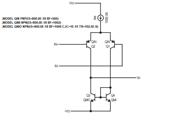
Why would Q3 and Q4 not have the same BF values in the picture of the Spice model i have attached?
-
\$\begingroup\$ If you told use where the circuit came from it would make it much easier to explain. \$\endgroup\$– Elliot AldersonCommented Dec 17, 2020 at 0:08
-
\$\begingroup\$ Part of Texas Instruments spice model for their LM311 comparator \$\endgroup\$– MarkCommented Dec 17, 2020 at 0:46
2 Answers
First, some clarifications. The LM311 SPICE model in question is from TI's website and is duplicated below:
* LM311 VOLTAGE COMPARATOR "MACROMODEL" SUBCIRCUIT
* CREATED USING PARTS VERSION 4.03 ON 03/07/90 AT 08:15
* REV (N/A)
* CONNECTIONS:   NON-INVERTING INPUT
*                | INVERTING INPUT
*                | | POSITIVE POWER SUPPLY
*                | | | NEGATIVE POWER SUPPLY
*                | | | | OPEN COLLECTOR OUTPUT
*                | | | | | OUTPUT GROUND
*                | | | | | |
.SUBCKT LM311    1 2 3 4 5 6
*
  F1    9  3 V1 1
  IEE   3  7 DC 100.0E-6
  VI1  21  1 DC .45
  VI2  22  2 DC .45
  Q1    9 21  7 QIN
  Q2    8 22  7 QIN
  Q3    9  8  4 QMO
  Q4    8  8  4 QMI
.MODEL QIN PNP(IS=800.0E-18 BF=500)
.MODEL QMI NPN(IS=800.0E-18 BF=1002)
.MODEL QMO NPN(IS=800.0E-18 BF=1000 CJC=1E-15 TR=102.5E-9)
  E1   10  6  9  4  1
  V1   10 11 DC 0
  Q5    5 11  6 QOC
.MODEL QOC NPN(IS=800.0E-18 BF=103.5E3 CJC=1E-15 TF=11.60E-12 TR=48.19E-9)
  DP    4  3 DX
  RP    3  4 6.667E3
.MODEL DX  D(IS=800.0E-18)
*
.ENDS
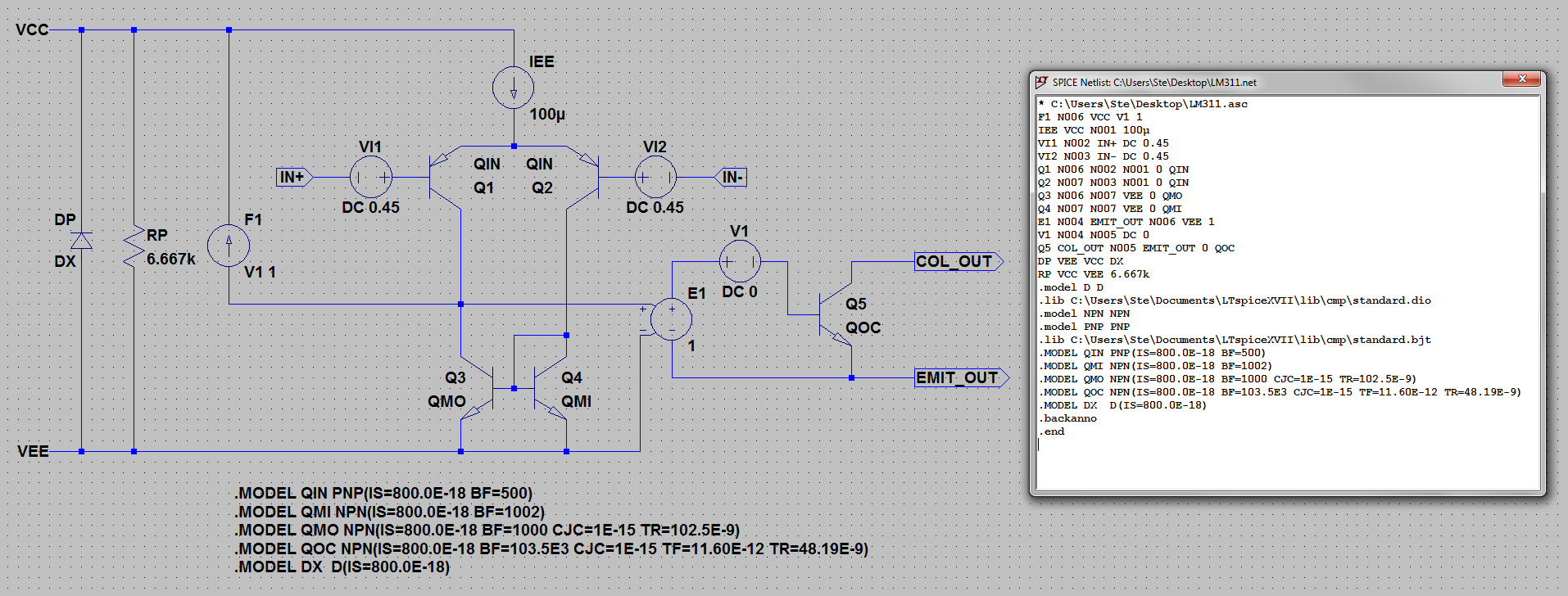
Since the subcircuit is simple enough, I "decompiled" its netlist back into a schematic so it's easier to see the entire context. The LTspice .asc file text is pasted below the image for anyone wishing to "download" this exact schematic.
Version 4
SHEET 1 1456 1424
WIRE -272 80 -320 80
WIRE -192 80 -272 80
WIRE -48 80 -192 80
WIRE 384 80 -48 80
WIRE 384 128 384 80
WIRE 384 256 384 208
WIRE 384 256 304 256
WIRE 464 256 384 256
WIRE 128 304 80 304
WIRE 240 304 208 304
WIRE 560 304 528 304
WIRE 688 304 640 304
WIRE -272 368 -272 80
WIRE -192 368 -192 80
WIRE -48 368 -48 80
WIRE 688 432 624 432
WIRE 800 432 768 432
WIRE 992 432 896 432
WIRE 896 464 896 432
WIRE 624 480 624 432
WIRE -48 496 -48 448
WIRE 304 496 304 352
WIRE 304 496 -48 496
WIRE 576 496 304 496
WIRE 800 512 800 432
WIRE 832 512 800 512
WIRE 464 544 464 352
WIRE 464 544 384 544
WIRE 304 576 304 496
WIRE 464 576 464 544
WIRE 624 608 624 560
WIRE 896 608 896 560
WIRE 896 608 624 608
WIRE 992 608 896 608
WIRE 384 624 384 544
WIRE 384 624 368 624
WIRE 400 624 384 624
WIRE -272 720 -272 432
WIRE -272 720 -320 720
WIRE -192 720 -192 448
WIRE -192 720 -272 720
WIRE 304 720 304 672
WIRE 304 720 -192 720
WIRE 464 720 464 672
WIRE 464 720 304 720
WIRE 576 720 576 544
WIRE 576 720 464 720
FLAG 80 304 IN+
IOPIN 80 304 In
FLAG -320 80 VCC
FLAG -320 720 VEE
FLAG 688 304 IN-
IOPIN 688 304 In
FLAG 992 432 COL_OUT
IOPIN 992 432 Out
FLAG 992 608 EMIT_OUT
IOPIN 992 608 Out
SYMBOL f -48 448 M180
WINDOW 0 24 80 Left 2
WINDOW 3 24 0 Left 2
SYMATTR InstName F1
SYMATTR Value V1 1
SYMBOL current 384 128 R0
SYMATTR InstName IEE
SYMATTR Value 100µ
SYMBOL voltage 224 304 R90
WINDOW 0 -32 56 VBottom 2
WINDOW 3 32 56 VTop 2
SYMATTR InstName VI1
SYMATTR Value DC 0.45
SYMBOL voltage 544 304 R270
WINDOW 0 32 56 VTop 2
WINDOW 3 -32 56 VBottom 2
SYMATTR InstName VI2
SYMATTR Value DC 0.45
SYMBOL pnp 240 352 M180
SYMATTR InstName Q1
SYMATTR Value QIN
SYMBOL pnp 528 352 R180
SYMATTR InstName Q2
SYMATTR Value QIN
SYMBOL npn 368 576 M0
SYMATTR InstName Q3
SYMATTR Value QMO
SYMBOL npn 400 576 R0
SYMATTR InstName Q4
SYMATTR Value QMI
SYMBOL e 624 464 R0
SYMATTR InstName E1
SYMATTR Value 1
SYMBOL voltage 672 432 R270
WINDOW 0 32 56 VTop 2
WINDOW 3 -32 56 VBottom 2
SYMATTR InstName V1
SYMATTR Value DC 0
SYMBOL npn 832 464 R0
SYMATTR InstName Q5
SYMATTR Value QOC
SYMBOL diode -256 432 R180
WINDOW 0 24 64 Left 2
WINDOW 3 24 0 Left 2
SYMATTR InstName DP
SYMATTR Value DX
SYMBOL res -208 352 R0
SYMATTR InstName RP
SYMATTR Value 6.667k
TEXT -40 784 Left 2 !.MODEL QIN PNP(IS=800.0E-18 BF=500)\n.MODEL QMI NPN(IS=800.0E-18 BF=1002)\n.MODEL QMO NPN(IS=800.0E-18 BF=1000 CJC=1E-15 TR=102.5E-9)\n.MODEL QOC NPN(IS=800.0E-18 BF=103.5E3 CJC=1E-15 TF=11.60E-12 TR=48.19E-9)\n.MODEL DX  D(IS=800.0E-18)
With this info, we can now address the question at hand. It's hard to determine exactly what the designer(s) had in mind, but we can take an educated guess by looking at the entire subcircuit. The first thing to point out is that the two NPN transistors form a current mirror. QMI seems to be "mirror in" and QMO seems to be "mirror out". The differences in model parameters between QMI and QMO are the BF (as you already pointed out), CJC, and TR.
It's easy to see why QMI doesn't have CJC and TR defined since they are both related to the capacitance model of the base-collector junction, where CJC is for the junction capacitance and TR is for the diffusion capacitance. Base and collector are shorted for this particular transistor, so it makes sense to leave these parameters at zero (the default) so the SPICE engine doesn't have to make extra calculations and slow the simulation down. For QMO, the TR of 102.5ns seems significant but the CJC is a measly 1fF (femto-farad) and is likely only added to aid in convergence since leaving it at zero can causes issues (especially back in 1990 when this model was written).
Going back to BF, we know that the performance of current mirrors is significantly affected by how well the two transistors are "matched". If you look at matched pair ICs (for example, the DMMT3904W from Diodes Inc), you can see they usually specify how well \$h_{FE}\$ (BF in this case) and \$V_{BE}\$ are matched. However, these devices usually have a BF mismatch range between 2% and 10%. The current mirror in the LM311 model only exhibits a tiny mismatch of 0.2% (1002/1000).
To conclude, my best guess is that the model designer wanted to add some intentional mismatch between the two transistors in order to model what you would typically get on physical part that comes off the production line and still falls within the "typical" datasheet specifications. Although 0.2% seems like a suspiciously low matching error, I don't know enough about IC design to give better insight beyond this. Alternatively, it could also be another convergence aid (similar to the CJC of 1fF above) where having the same exact BF=1000 values on the mirror caused a simulation anomaly that breaks the model.
-
1\$\begingroup\$ Thank you for spending the time. Yes it is strange that someone went to this level on the BF mismatch in the current mirror. I can't seem to find how this would effect various traces i have run and the model actually does not reproduce the datasheet values that well. Another puzzle is voltage sources VI1 and VI2 both at 0.45 volts. Some have suggested this to simulate common-mode input voltage range restrictions ... but not very well. Any idea on these? \$\endgroup\$– MarkCommented Dec 17, 2020 at 16:21
-
\$\begingroup\$ @Mark Sorry, not sure. One thing to try is building the schematic found in the datasheet (on Page 10) within SPICE and compare its performance to the macromodel as you tweak things such as the DC voltage sources in question. \$\endgroup\$ Commented Dec 17, 2020 at 20:38
-
\$\begingroup\$ thanks. Also, LM111, LM139 and LM119 use the same BF's as this current mirror. They also use those two VI1 and VI2 sources but some with different values. \$\endgroup\$– MarkCommented Dec 17, 2020 at 21:01
-
\$\begingroup\$ @Mark That makes sense. What was commonly done back then is come up with a generic topology and release different models with tweaked parameters for each part. They still do this today, but some topologies like Green-Williams-Lis have become much more sophisticated. Anyway, this kind of approach is why I think the UniversalOpamp2 in LTspice is so useful. \$\endgroup\$ Commented Dec 18, 2020 at 8:19
-
\$\begingroup\$ Maybe some will run into these same questions as mine when looking at them as well. Hopefully the reason for these becomes clear. Thanks for the help. \$\endgroup\$– MarkCommented Dec 18, 2020 at 13:33
It is ideal maximum forward Beta koeff, so you could play with it... it's almost never the same in real. Looks someone adjusted it for some exact curve this case (they are connected differently, some perfectionist did the tuning). Think, you could make them the same without any issue :) I would also maybe recommend this to read: https://class.ece.uw.edu/cadta/hspice/chapter_14.pdf
-
\$\begingroup\$ This is from the spice model for Texas Instruments LM311 comparator. \$\endgroup\$– MarkCommented Dec 17, 2020 at 0:43

