1
\$\begingroup\$

I have a device (NXQ1TXH5) that I want to run at 5V. I am also interfacing this device with a Raspberry Pi4 for i2c communication. This raspberry pi 4 is going to be the master in my i2c network. This runs at 3v3.

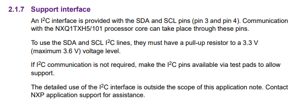
As the title says, I want to pull up SDA/SCL to 3V3, as required by the datasheet (although the device can take up to 5v, the SDA/SCL only works with 3v3 (maximum 3.6V)).

Datasheet mentioning 3v3 enter image description here

I could use a voltage regulator to step down from 5V to 3v3.t would require some filtering capacitor and more complex assembly

The second option is a voltage divider. Would a voltage divider do the trick here, given that the 5V source will be constant? (it's cheaper, although it might be less efficient)

If yes, what values?

\$\endgroup\$
4
  • 5
    \$\begingroup\$ If everything on the board runs on 5V, why do you wat to use a voltage divider? \$\endgroup\$
    – brhans
    Commented Dec 22, 2020 at 1:44
  • 3
    \$\begingroup\$ Yes this is confusing. Often, the best solution for I2C, assuming a single master, is to externally pull up SDA and SCL to the master IC's VCC, which, from your post, sounds like it is 5V. If not, maybe you can update your question with more information such as a list of all IC's on the I2C bus, their role (master or slave) and the VCC used by that IC. \$\endgroup\$
    – user57037
    Commented Dec 22, 2020 at 1:50
  • \$\begingroup\$ "However, the IC I am using requires 5V intake" - which IC is that? \$\endgroup\$ Commented Dec 22, 2020 at 6:57
  • 1
    \$\begingroup\$ This is still confusing. Pi and the wireless coil chip seem to be 3.3V IO chips and need 3.3V bus and do not tolerate 5V IO. The 5V chips then again may not work with 3.3V bus voltage. Please clarify more what chips and devices you have connected and how. And Pi has 3.3V already available for pullups. \$\endgroup\$
    – Justme
    Commented Dec 22, 2020 at 18:28

2 Answers 2

4
\$\begingroup\$

The best option, when possible, especially in the case where there is a single I2C master, is to pull up to the same VCC as the I2C master. In your application that would be the Raspberry Pi VCC, I guess.

But it is still an interesting question. The basic answer is, yes, you can use a divider for pullup.

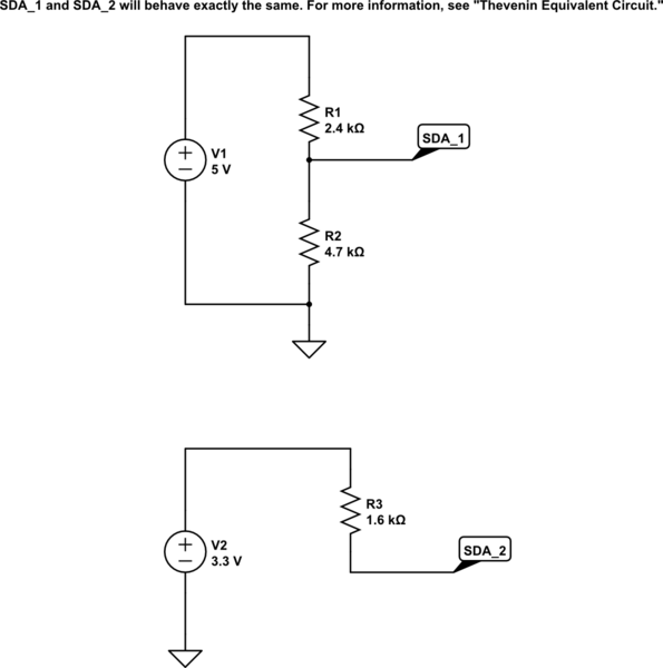
The effective pullup voltage is V * R2 / (R1+R2) where R1 is the upper leg of the divider and R2 is the lower leg of the divider. The effective pullup resistance is R1 in parallel with R2, which is (R1*R2)/(R1+R2).

schematic

simulate this circuit – Schematic created using CircuitLab

Note that the divider will consume power even when SDA and SCL are not pulled down. In micropower designs, the divider approach may not be the wisest option for that reason. An option (a bit odd, but potentially workable) would be to use a low quiescent current (Iq) linear regulator (possibly an LDO) to generate the 3.3V for the pullups. I have never seen this or had to resort to it, so I suspect it is not commonly needed.

\$\endgroup\$
3
  • \$\begingroup\$ I updated my question. Your answer is still relevant. I now understand that there is no difference between SDA_1 and SDA_2. I was wondering whether there's any problem in using the divider instead of step-down regulator. From a design point of view, 4 resistors to split the voltage across two lines is simpler and cheaper than employing a regulator. What do you think? Btw, this is not going to run on a battery, but on a 40W transformer, so there's enough power. \$\endgroup\$
    – bem22
    Commented Dec 22, 2020 at 15:02
  • 1
    \$\begingroup\$ If power is not a concern I would use a divider. But my first choice would be to find where on the Raspberry Pi board the 3.3V is coming from and pull up to that 3.3V. That way you don't need a regulator OR a divider. If the Raspberry Pi I2C runs at 3.3V, there must be 3.3V available on the Raspberry Pi board somewhere. \$\endgroup\$
    – user57037
    Commented Dec 22, 2020 at 18:24
  • \$\begingroup\$ Thanks mkeith. Really good tip. I will use the 3v3 from the pi! \$\endgroup\$
    – bem22
    Commented Dec 22, 2020 at 19:09
1
\$\begingroup\$

I was wondering whether there's any problem in using the divider instead of step-down regulator.

A step-down regulator (Switching regulator) is better or required when the Power Dissipation using a voltage divider circuit or a Linear Voltage Regulator, is too high.

For example when you are powering a device from a much higher voltage source. With a 20V difference, even 100mA can generate enough power dissipation to consider using a step-down regulator.

In another example, using a voltage divider circuit or a Linear Voltage Regulator when you need to convert 5V to 3V for an application consuming more less 100mA is fine.

If the goal is to provide a 3V signal to an ic input, it's also fine since it consumes very little. In the case of signal input, in order to limit current consumption, use high value resistors in your voltage divider: 22K or more. 100K is a common value. The total value between source to ground defines the power loss.

The main difference between a voltage divider circuit made off two resistors and a Linear Voltage Regulator (LDO or non-LDO) is that the Linear Voltage Regulator will always output the same voltage regardless of the input voltage whereas the resistor divider will only divide, not regulate the voltage. If the input voltage is higher, the output voltage will also be higher, proportionally, with a divider. If your source voltage is constant and regulated, a divider is ok.

Linear Voltage Regulators also offer additional protections that you may want to consider. But high value resistors also protects the circuits effectively.

\$\endgroup\$

Your Answer

By clicking “Post Your Answer”, you agree to our terms of service and acknowledge you have read our privacy policy.

Not the answer you're looking for? Browse other questions tagged or ask your own question.