0
\$\begingroup\$

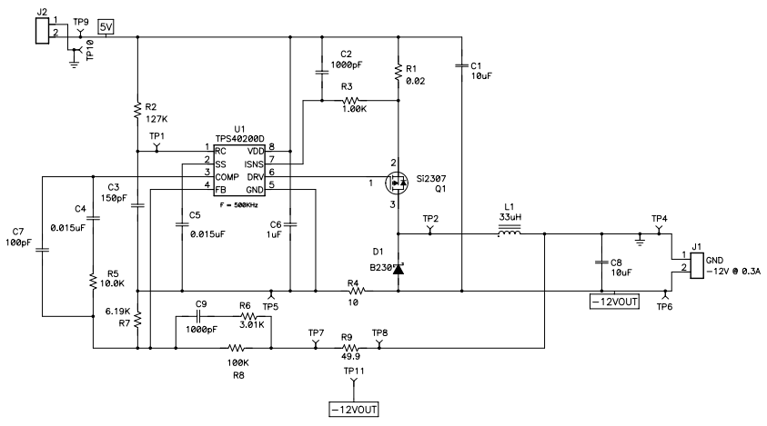
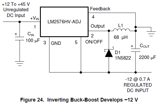
I saw two schematics for inverter switching converters for -12V output. I wonder, the first schematic uses many components compared to the second one but still, the output current rating of 2nd one is more. Is it safe to use 2nd one? Won't there be any problem if I implement the 2nd one on the PCB?

  1. Using TPS40200 and the link is here: https://www.ti.com/tool/PMP1903#technicaldocuments enter image description here
  2. Using LM2576 and the diagram is in pg-19 in the datasheet: https://www.ti.com/lit/ds/symlink/lm2576.pdf?ts=1608612202416&ref_url=https%253A%252F%252Fwww.google.com%252F enter image description here
\$\endgroup\$

1 Answer 1

0
\$\begingroup\$

They are both using a buck converter in inverting buck-boost configuration, which ties the buck output to ground and takes the output from what would be the ground connection of the buck.

That's a perfectly good topology, so either one will work. The difference is the first circuit uses an older buck controller with external FET and diode, which gives more flexibility for loop compensation, selection of FET/diode for your requirements, and soft-start.

The bottom circuit uses an integrated FET Simple Switcher that is meant to be easy to use, but you have to deal with what you get for loop response and start up.

Both would need a level shifting circuit if you wanted to control the enable to turn the converter on and off, because the part's enable is now referenced to the output, not ground.

\$\endgroup\$

Your Answer

By clicking “Post Your Answer”, you agree to our terms of service and acknowledge you have read our privacy policy.

Not the answer you're looking for? Browse other questions tagged or ask your own question.