0
\$\begingroup\$

I'm trying to understand the description of a counter in VHDL:

entity counter is port ( 
    load, reset, clk: in bit; 
    input: in integer range 0 to 255; 
    output: out integer range 0 to 255);
end counter;

architecture behaviour of counter is 
begin
   ctr: process
      variable value: integer range 0 to 256 := 0;
      begin
         --update value
         if(clk'event) and (clk= '1') then 
            value := value + 1;
         elsif load= '1' then value := input; 
         elsif reset = '1' then value := 0;
         end if;
               
         if value = 256 then value:= 0; end if;
         
         --output value
         output <= value;
         
         --wait on changes in input signals
         wait on clk, load, reset;
   end process;
end behaviour;

but I don't really get it. There are a lot of examples of counters out there but each is one is completely different from the other and meanwhile, I don't know where to get answers. This entity will be used along with this testcounter:

entity testcounter is end testcounter;

architecture behaviour of testcounter is 

   component counter port( 
      load, reset, clk: in bit; 
      input: in integer range 0 to 255; 
      output: out integer range 0 to 255
   );
   end component;

   signal load, reset, clk: bit;
   signal input: integer range 0 to 255; 
   signal output: integer range 0 to 255;
   begin DUT: counter port map(load, reset, clk, input, output);
   
   --Simulation.
   process
   begin
      --Simulation: Load.
      for c in 0 to 255 loop
         input <= c;
         wait for 25 ns;
         load <= '1';
         wait for 50 ns;
         load <= '0';
         wait for 25 ns;
         assert input= output report "Load: output wrong";
      end loop;
      
      --Simulation: Reset.
      reset <= '1';
      wait for 50 ns;      
      reset <= '0';
      wait for 25 ns;
      assert output = 0 report "Reset: output wrong";
      
      --Simulation: Count. 
      for c in 0 to 255 loop
         assert c = output report "Count: output wrong";      
         clk <= '0';
         wait for 25 ns;
         clk <= '1';
         wait for 50 ns;
         clk <= '0';
         wait for 25 ns;
      end loop;
      assert output = 0 report "Count: overflow wrong";
      
      --Simulation: Reset.
      reset <= '1';
      wait for 50 ns;      
      reset <= '0';
      assert output = 0 report "Reset: output wrong";
      
      wait;
  end process;
end behaviour;

but I'm fine if I could get help understanding the counter. I have seen several descriptions and I think I know how counters work conceptually but lack the knowledge how to implement them. I understand programming itself but I don't get the meaning of the clock, load and reset and their results when the one is zero or one. Could somebody explain? I'm also glad if you could point me to proper sources where I can look that up!

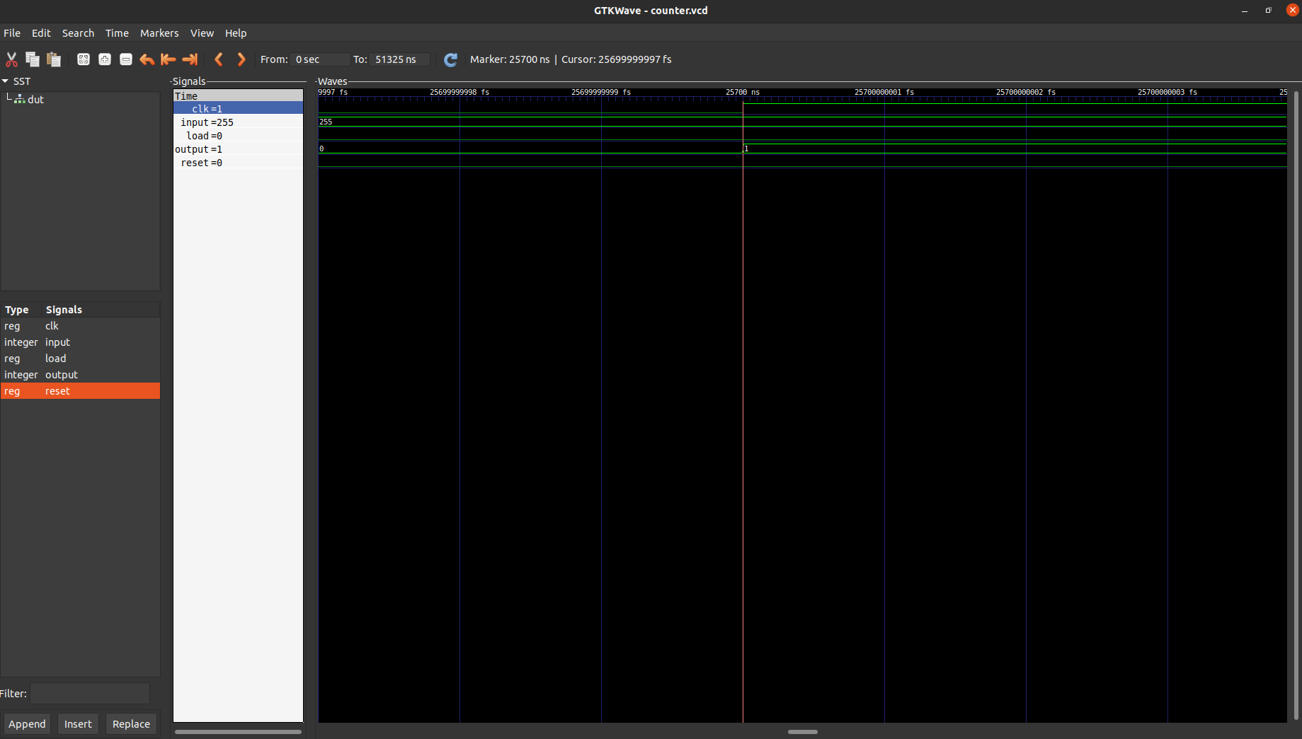
added gtkwave: img

\$\endgroup\$
13
  • \$\begingroup\$ Where on earth did you find that example? It's awful. \$\endgroup\$
    – user16324
    Commented Dec 22, 2020 at 19:19
  • \$\begingroup\$ Why did you come across VHDL and what is your background? It seems like you're missing some essential aspects of it... \$\endgroup\$
    – po.pe
    Commented Dec 22, 2020 at 19:26
  • \$\begingroup\$ @BrianDrummond Really? It's from the modul I'm attending. It's a single course about hardware&software from a state university. \$\endgroup\$
    – Ben
    Commented Dec 22, 2020 at 19:36
  • \$\begingroup\$ @po.pe Yep, that's true :) As I wrote, it's part of a modul, the second from around 15 topics. Apparently, they demand too much (for me). However, I would like to learn it nevertheless. \$\endgroup\$
    – Ben
    Commented Dec 22, 2020 at 19:38
  • 1
    \$\begingroup\$ While using wait on statement works, I don't recommend it as a good coding style. By the way, looking at your code, I think you should revisit the fundamentals for eg: how to design a D flip-flop in vhdl/verilog. Use ug901 xilinx vivado synthesis guide as the reference to start with (if it's xilinx FPGA). \$\endgroup\$
    – Mitu Raj
    Commented Dec 23, 2020 at 13:57

1 Answer 1

1
\$\begingroup\$

The first and probably most important thing with VHDL is to understand that it's not a programming language but a hardware description language. You're not writing sequential code blocks but rather describe logical and combinatorial hardware.

It depends a little how deep you wanna dive into this topic, but you could read something about counter implementation using logic gates.

What your counter does is it evaluates the value of value with every rising edge of the incoming clock. This is another speciality of VHDL, where in sequential programming language the clock is something you don't really see, it's a crucial part of every VHDL design.

Regarding your example, as already stated by Brian Drummond, that's not really proper code. Your process needs a sensitivity list to be simulated. A sensitivity list tells the simulator what signals it has to watch for re-evaluating the process. In your case this would be clk, load and reset.

\$\endgroup\$
5
  • 1
    \$\begingroup\$ You CAN run a process without a sensitivity list, using "wait on" to suspend the process. But it's ... odd ... and the asynchronous load and the off-by-one range bodge with asynchronous clear is even odder. Probably a good way of finding synthesis tool bugs though. \$\endgroup\$
    – user16324
    Commented Dec 22, 2020 at 19:41
  • \$\begingroup\$ Thanks a lot! I've seen e.g. geeksforgeeks.org/counters-in-digital-logic but I can't really see how clk, load and reset behave there. Neither on other resources. Could you maybe mention some more specific keywords I could use to find proper material? I cannot judge the code itself but I can see it looks very different from other implementations I find online - but they differ among each other quite a lot as well. However, thrown in gtkwave it seems to work. But I can't really see or learn something there. I just clock edges.. \$\endgroup\$
    – Ben
    Commented Dec 22, 2020 at 19:42
  • \$\begingroup\$ @BrianDrummond: Interesting, never really thought about it, but it makes sense. Is it an equivalent from a synthesis point of view? Still I would suggest to use a proper sensitivity list instead. \$\endgroup\$
    – po.pe
    Commented Dec 23, 2020 at 7:51
  • \$\begingroup\$ In this case I'll go with no, as you need two asynchronous inputs and clock, not just the standard (clock,reset). And I can't think of any FPGA tech that reliably provides that (prioritising Set over Reset). Delete Load (or make it synchronous) and ... potentially yes. But you're relying on synth tool authors to have (a) bothered to implement it, (b) got it right and (c) tested it : a lot of work to support a very rare usage. So, ... probably not. I'd encourage the OP to test it. \$\endgroup\$
    – user16324
    Commented Dec 23, 2020 at 11:22
  • \$\begingroup\$ @BrianDrummond I honestly wouldn't, beginners that test atrocities like this will inevitably get stuck again and again, keep on needing help from forums like this and all that´s needed to have all their invested time go to waste is one question that isn't answered. Bad code like this should be tested by people that have a clue how to debug it independently, not by the ones that are just at the entry level and want to progress to actually learning relevant stuff. \$\endgroup\$
    – DonFusili
    Commented Dec 30, 2020 at 9:05

Your Answer

By clicking “Post Your Answer”, you agree to our terms of service and acknowledge you have read our privacy policy.

Not the answer you're looking for? Browse other questions tagged or ask your own question.