0
\$\begingroup\$

Will this cause any significant issues in delay or performance? Intuitively, I think the addition of a big switch on the trace will add additional inductance/capacitance, but is there a way I can better estimate the effects?

For reference, the transition and propagation time from the gate is ~10ns. Given my circuit is fairly sensitive to delays, would I be better off using 0 ohm resistors and solder/de-solder every time I want to switch?

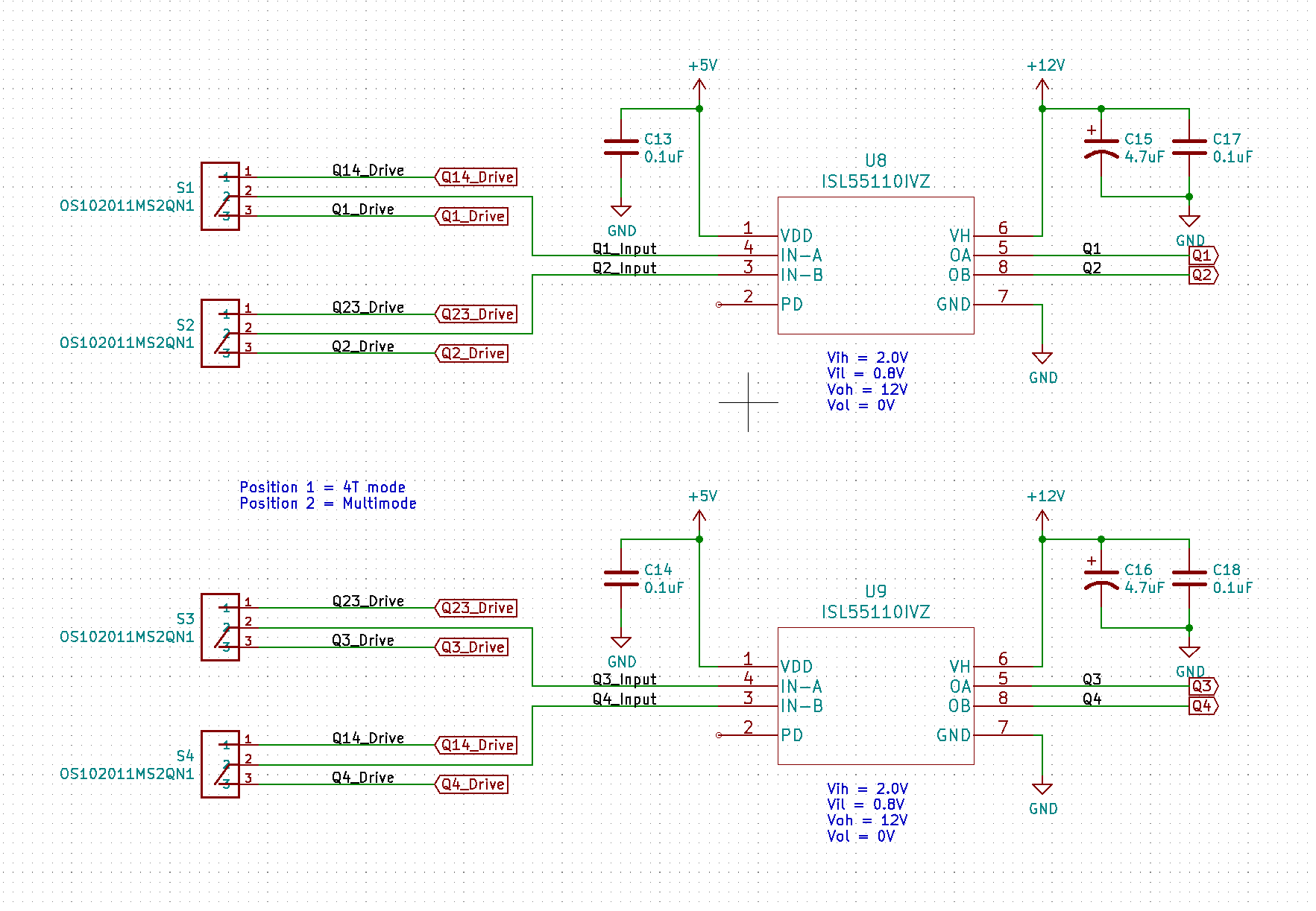
Edit: Added schematic.

\$\endgroup\$
5
  • 2
    \$\begingroup\$ you've told us what you feed into the switch, but not what you do with the signal after the switch. While EMI-wise, this sounds not great, it's hard to guess signal integrity effects without knowing what consumes the signal. Also: do you only switch in non-operation? \$\endgroup\$ Commented Dec 23, 2020 at 9:38
  • 1
    \$\begingroup\$ Please add a schematic of your planned circuit. \$\endgroup\$ Commented Dec 23, 2020 at 14:45
  • \$\begingroup\$ "would I be better off using 0 ohm resistors and solder/de-solder every time I want to switch?" Have you considered a 2 pin header with a removable jumper? Or even two closely spaced solder pads that you can bridge with solder? \$\endgroup\$ Commented Dec 23, 2020 at 18:48
  • \$\begingroup\$ Thanks for the responses, I've added an image of my schematic. @Marcus Müller I'm planning to feed the signal into a gate driver IC. The switching will only occur during non-operation. That's also a great point about the jumper! A jumper on a header seems like the best hybrid option between a mechanical switch and 0 ohm resistor. Given I might be switching a few times during testing, I'd prefer to avoid reworking the board if possible. \$\endgroup\$
    – brian
    Commented Dec 23, 2020 at 20:35
  • 1
    \$\begingroup\$ hm, so, this is not a high-powered, and purely binary, signal, right? so, a couple-of-cents switch IC would do perfectly well, and you can select which output that drives with any switch you want, no matter the bandwidth. \$\endgroup\$ Commented Dec 23, 2020 at 20:58

1 Answer 1

1
\$\begingroup\$

Yeah, so a signal with a 10 ns rise time will have, if you want to keep it similarly sharp have to have at least 5×, better 7× or more bandwidth than 1/(rise time). This rule of thumb comes from the series expansion of the square wave of frequency 1/(rise time).

You will probably have not much trouble with the cleanliness of your edge even if you use a big chunky switch, but you'll radiate stuff like crazy.

On the other hand, the soldering is clearly overkill: Switches meant for such bandwidths do exist. For example:
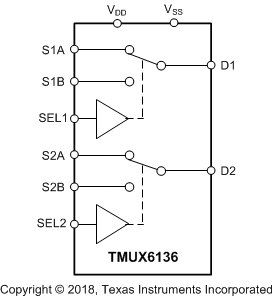
TMUX6136

Use your manual switches to control the SEL inputs.

This specific device probably won't fit your voltage range requirements (you don't specify). You got to pick one multiplexer fit for your application – there's literally hundreds to choose from at the distributor's websites (Farnell/element14, digikey, rs components...).

In all honesty, though, it might be simpler to simply have amplifiers / buffers that you switch to a high-Z output mode. In all likelihood, you could even use mature, but advanced 74xx logic like the SN74AUP1T157; nothing too fancy.

General recommendation: Make sure you really need the 10 ns rise time. While far from impossible, I wonder whether a Schmitt trigger on the gate driver (integrated or external but geometrically close) wouldn't relax your bandwidth requirements significantly and thus allow you to increase rise time, making your system less prone to EMI.

\$\endgroup\$

Your Answer

By clicking “Post Your Answer”, you agree to our terms of service and acknowledge you have read our privacy policy.

Not the answer you're looking for? Browse other questions tagged or ask your own question.