1
\$\begingroup\$

enter image description here

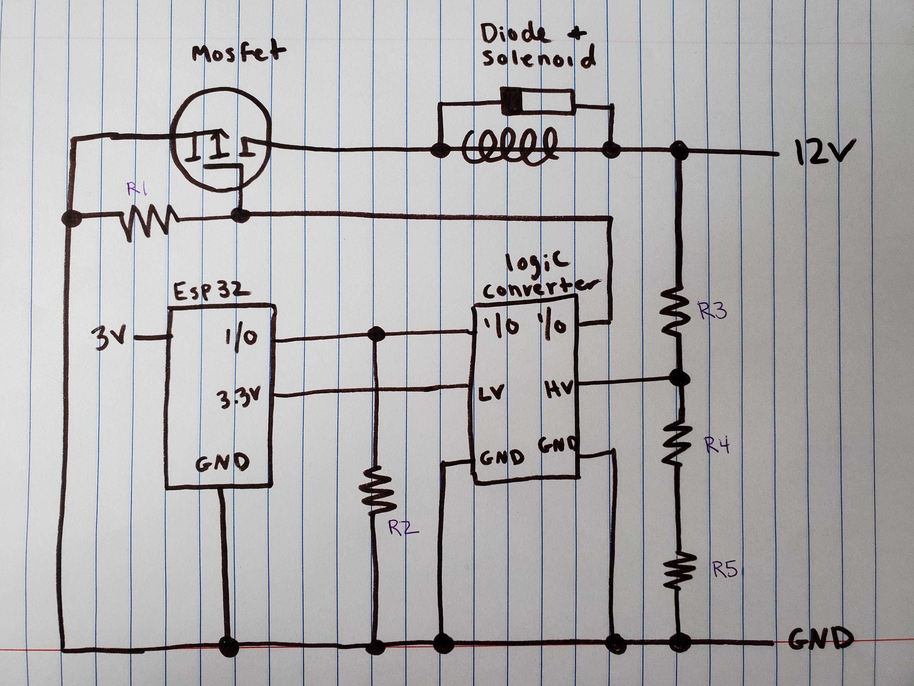
I am wondering if anyone can comment on the feasibility of this circuit. My ultimate goal is to switch a 12V solenoid on and off using a 3.3V microcontroller, but I have had trouble so far. I want to switch the solenoid on when the I/O pin goes high, and the solenoid to switch off when the I/O pin goes low. I am trying to find the simplest way to do this.

I bought a logic level mosfet with the original intention of driving the mosfet gate directly with the 3.3V I/O pin of my microcontroller, but the mosfet does not open enough to drive the solenoid. I have tried a few different types of logic level mosfets, but I have not had luck finding one that opens with just a 3.3V. I do know that applying 5V to the mosfet gate opens the gate enough to drive the solenoid.

I am hoping to use a logic level converter to boost the 3.3V output to something higher. Below is the circuit I am planning on using. I am hoping that this setup will work, but I wanted to hear input if I am misunderstanding something before purchasing products/soldering.

I have purposely left the resistance values off the resistors below, because I am open to input. The setup is as below:

  • R3 = R4 = R5 (1k ohms?) This is a voltage divider that will apply 8V to the converter.

  • R1 is a pulldown to keep mosfet gate low (10k ohms?)

  • R2 is a pulldown to keep the I/O pin low (10k ohms?)

  • Microcontroller = ESP32 (There is a mistake in the diagram. ESP32 is powered by 3.3V, not 3V)

  • Logic Converter = BSS138 (maximum High Voltage is 10V, minimum Low Voltage is 1.8V)

  • Solenoid = 2 amp, 12 Volt

  • Mosfet = IRLZ44N (RDSon is 5 Volts @0.025 ohms. Gate threshold is 1 - 2 volts). I also have some TIP120 transistors

Thank you.

\$\endgroup\$
6
  • \$\begingroup\$ Try looking for a MOSFET gate driver.. And your diode seems to be the wrong way round. \$\endgroup\$
    – RoyC
    Commented Dec 26, 2020 at 20:46
  • \$\begingroup\$ @RoyC I will look into a gate driver. Thank you for letting me know about the diode. I will wire it correctly when I actually build the circuit. \$\endgroup\$ Commented Dec 26, 2020 at 21:17
  • \$\begingroup\$ @Unimportant If I understand you correctly, I actually have this as my "backup option". Using two NPN transistors to apply and remove voltage from the Mosfet gate. I was wondering if what you suggested is more robust than using the logic level converter I show in this post. I would do something similar to this: i.sstatic.net/18EJ1.gif \$\endgroup\$ Commented Dec 26, 2020 at 21:21
  • \$\begingroup\$ @domerwannabe Yes, that should work. Assuming you just need to turn the solenoid on and off, not PWM it at high speed or something. \$\endgroup\$ Commented Dec 26, 2020 at 21:25
  • \$\begingroup\$ @Unimportant. Thank You. This solenoid will just be going on and off to open a door, so speed is not important. This is just a DIY project. I already have some 2N2222A transistors as well. \$\endgroup\$ Commented Dec 26, 2020 at 21:33

1 Answer 1

1
\$\begingroup\$

It might be worth looking into isolated low-side gate drivers, which effectively accomplish what you want to do, and can provide decent protection to your ESP32 (against transient voltages / part damage on the FET or driver). A bunch of options come up if you look up “gate-driver” on digikey / mouser, and you can go through your options there. Since you aren’t doing a half bridge, you can get away with just using “low-side” drivers which will save you a fair amount of money. Isolation isn’t a necessity, but is definitely much safer for your MCU.

Also, with respect to the circuit you drew, don’t try to generate your “HV” voltage like that. Those drivers are generally meant to drive a lot of current to charge the FET gate up quickly, and the divider will have to much resistance which won’t allow the part to turn on very fast. It might still work, but don’t expect it to turn on super fast.

Side note: Your MOSFET is drawn as a P-Channel, and the diode isn’t drawn super precisely, but just make sure that the cathode is definitely connected to the 12V rail.

\$\endgroup\$

Your Answer

By clicking “Post Your Answer”, you agree to our terms of service and acknowledge you have read our privacy policy.

Not the answer you're looking for? Browse other questions tagged or ask your own question.