0
\$\begingroup\$

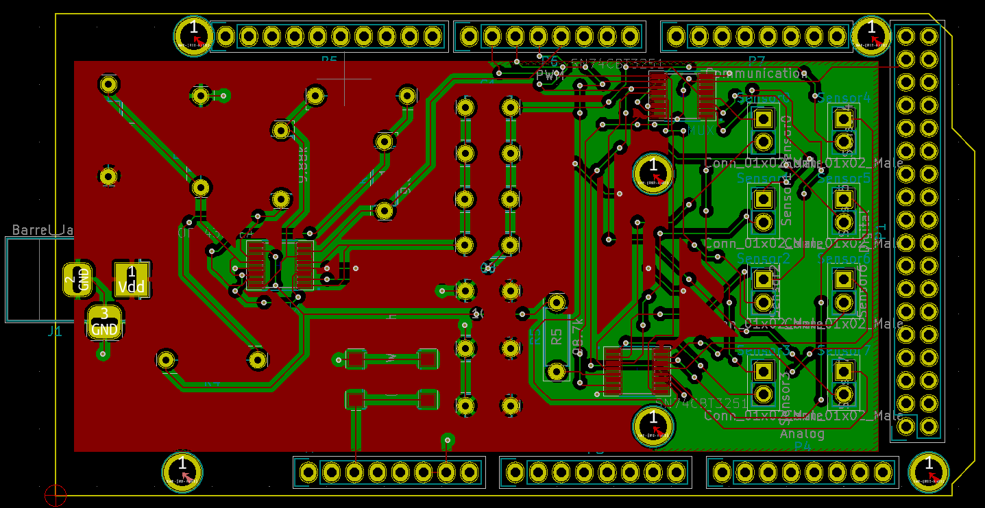
I made an Arduino shield with KiCAD.

When I finished the board in PCBnew, I ran a design rules check.

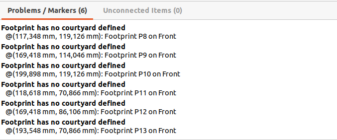
I got "Footprint has no courtyard defined" on all the mounting holes in the shield template.

This is a picture of the PCB:

enter image description here

This is a picture of the errors, with the mounting holes:

enter image description here

\$\endgroup\$
4
  • 1
    \$\begingroup\$ Well, did you define a courtyard on the mounting hole footprint? Either way, that's odd; I've never seen that error before, and I know I've forgotten courtyards on footprints. \$\endgroup\$
    – Hearth
    Commented Dec 28, 2020 at 14:25
  • \$\begingroup\$ @Hearth to be honest.. This is the first time i hear about courtyards and i don't know what they are, or how to define them \$\endgroup\$ Commented Dec 28, 2020 at 14:39
  • \$\begingroup\$ Did you make the shield template, or did you use an existing template (or footprint) that you downloaded somewhere? \$\endgroup\$
    – JRE
    Commented Dec 28, 2020 at 14:41
  • \$\begingroup\$ I used the template that KiCAD offers. \$\endgroup\$ Commented Dec 28, 2020 at 14:51

2 Answers 2

3
\$\begingroup\$

If you look at the other footprints on your photo, there's a thin white border around them. That's most probably the courtyard.

KiCAD uses that layer to check if two different footprints are overlapped. Edit the mounting hole's footprint, select the F.CrtYd and B.CrtYd layers and add a graphic circle large enough to encompass all the island. That will remove the warnings.

\$\endgroup\$
3
\$\begingroup\$

The courtyard is the area that the physical component will be in. This is defined in IC’s to make sure they won’t collide when you solder the components.

There’s a design rule check mark somewhere that makes it give an error if a component doesn’t have a courtyard defined. The template designers probably imported/converted the footprint for the screws or were too lazy to draw a courtyard. In your case, it does not hurt if the screws have no courtyard defined, since you’ll know the size of the screw by head. If this is your final design, and the errors only are for the screws, you can safely turn the checkmark off. I’ll try to fire up kicad if you cannot find it yourself. Another solution would be to edit the footprint to include a courtyard (draw it the size of the screw head), or to choose a screw footprint that is equivalent that does have a courtyard defined.

\$\endgroup\$
4
  • \$\begingroup\$ Thanks.. Still not very clear to me. I have to note i used KiCAD's arduino mega shield template. As far as design rules, i plan to use jlcpcb as the manufacturing company, so i used this template (for 2 layers boards) for the rules. Is my pcb ok if i send it for manufacturing? I don't plan on using screws anyway. \$\endgroup\$ Commented Dec 28, 2020 at 14:54
  • \$\begingroup\$ @user1584421 the setting is found in file > board setup > design rules > require courtyard definitions in footprints. You have to understand that this takes away a small part of the design rule check, so that when components do overlap, KiCad won’t notify you. For adding the courtyard instead of disabling the check, see Otávio’s answer \$\endgroup\$
    – Ananas_hoi
    Commented Dec 28, 2020 at 15:00
  • \$\begingroup\$ So i guess it will be ok if i send it to the board house as it is? \$\endgroup\$ Commented Dec 28, 2020 at 15:28
  • \$\begingroup\$ @user1584421 this is not going to pose a problem no, as you mentioned not using the screws anyway. \$\endgroup\$
    – Ananas_hoi
    Commented Dec 28, 2020 at 15:30

Your Answer

By clicking “Post Your Answer”, you agree to our terms of service and acknowledge you have read our privacy policy.

Not the answer you're looking for? Browse other questions tagged or ask your own question.