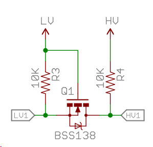
I would like to turn off and on a servo while it is not used. The LV would be 3.3V and the HV would be connected directly to s lithium battery. Could it work if I replace R4 with a servo? What problem I might face?
-
\$\begingroup\$ R4 is a problem you might face. This circuit works for logic signals, it doesn't work for power supplies. To turn off a power supply you need a different circuit. \$\endgroup\$– Criticizing Israel not allowedCommented Dec 29, 2020 at 19:55
-
\$\begingroup\$ I am using the one proposed here: electronics.stackexchange.com/a/321851/4705 . Things looks nicer and less error pron withouth my soldering. Any available board which I can use and has a low RDSon? \$\endgroup\$– MokusCommented Dec 29, 2020 at 20:21
-
\$\begingroup\$ Are you talking about using an output to drive the POWER line of a model aircraft servo? It's unlikely that you'll get enough current. You might be able to drive the PWM pin. \$\endgroup\$– Scott SeidmanCommented Dec 29, 2020 at 20:23
-
\$\begingroup\$ I added temperature and humidity sensor to my beehive running on batteries. And I would loke to open/close a hatch if the tempersture goes above a ceetain level. I am experimenting with the SG90 servo. \$\endgroup\$– MokusCommented Dec 29, 2020 at 20:30
3 Answers
Use an inverter/level shifter driving the gate of a P-channel FET, and make sure to turn the PWM signal to the servo off when you turn the servo itself off. It'll take a couple more components, but it'll Just Work.
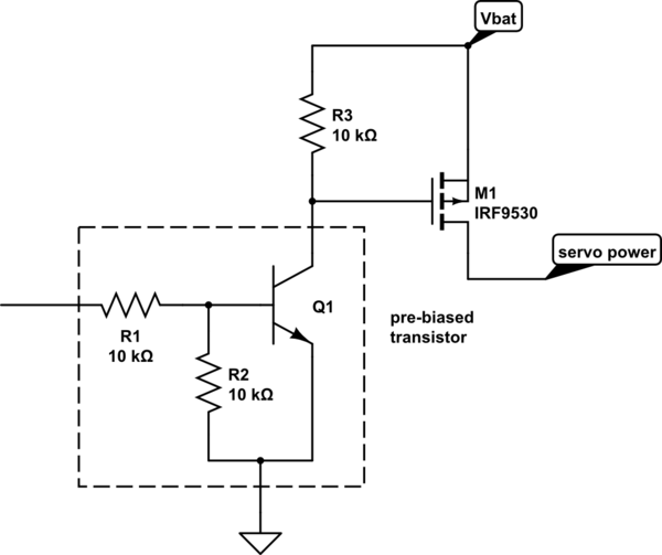
The circuit shown uses a SOT-23 (or smaller) pre-biased transistor and fewer resistors than what you have.

simulate this circuit – Schematic created using CircuitLab
-
\$\begingroup\$ Any available board which I can use and has a low RDSon? I am already built such a circuit but I am not so confotable with soldering. \$\endgroup\$– MokusCommented Dec 29, 2020 at 20:25
-
\$\begingroup\$ That I don't know. You called out a FET that comes in surface mount, so I assumed it would work for you. \$\endgroup\$ Commented Dec 29, 2020 at 20:32
-
\$\begingroup\$ You could do this with discrete through-hole components, but you'd still need to do some soldering -- and I don't know of anyone that makes pre-biased through-hole transistors. \$\endgroup\$ Commented Dec 29, 2020 at 20:38
Many problems. That circuit is a level shifter for data signal, so it is not a power switch. Basically if it tries to turn on a servo, the high supply return currents would go into MCU IO pin, so it would not work, and could even be damage the MCU.
Also even if the transistor is used in a proper way to disconnect servo ground, the problem is that when a device has both data and power supplies connected to it, it is not a good idea to disconnect ground, but the positive supply.
-
\$\begingroup\$ If this tries to turn on a signal, the supply current will go through R4 and make the voltage for the servo nearly 0. \$\endgroup\$ Commented Dec 29, 2020 at 20:44
You might be ok with this if you connect LV1 to ground and LV to the IO pin. However a BSS138 is only rated for 220mA so check the stall current for the servo. There’s also the problem of the control pin of the servo - you haven’t shown this part of the circuit and you’d need a similar low-side switch so the control input doesn’t drop below the servo ground when it’s switched off.

