0
\$\begingroup\$

I am trying to build a waveform amplifier with a gain of 10 to amplify the voltage coming from a signal generator because its maximum output is 10 Vpp.

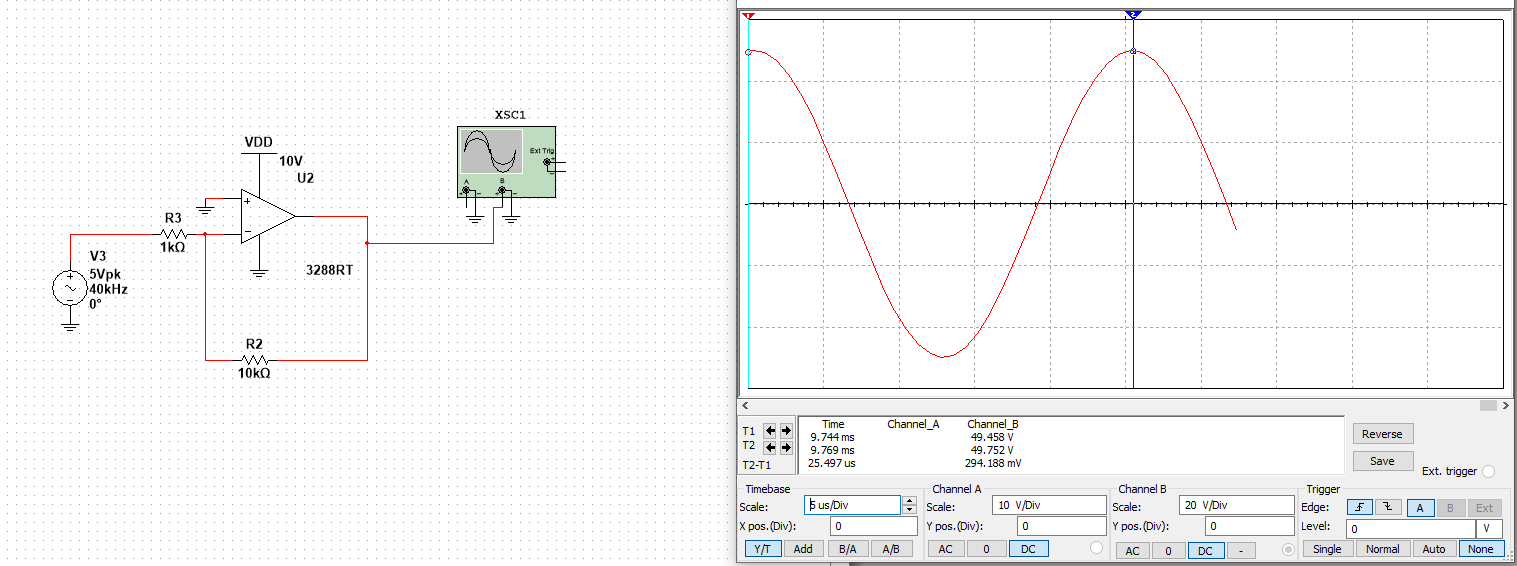
The simulation works:

enter image description here

As expected, I am seeing a gain of 10.

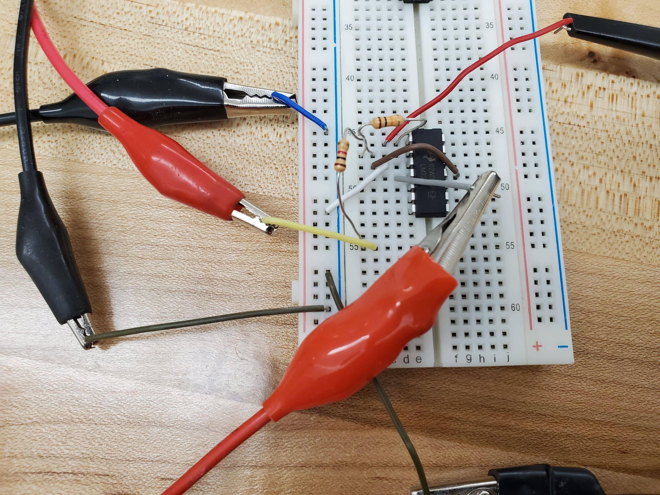
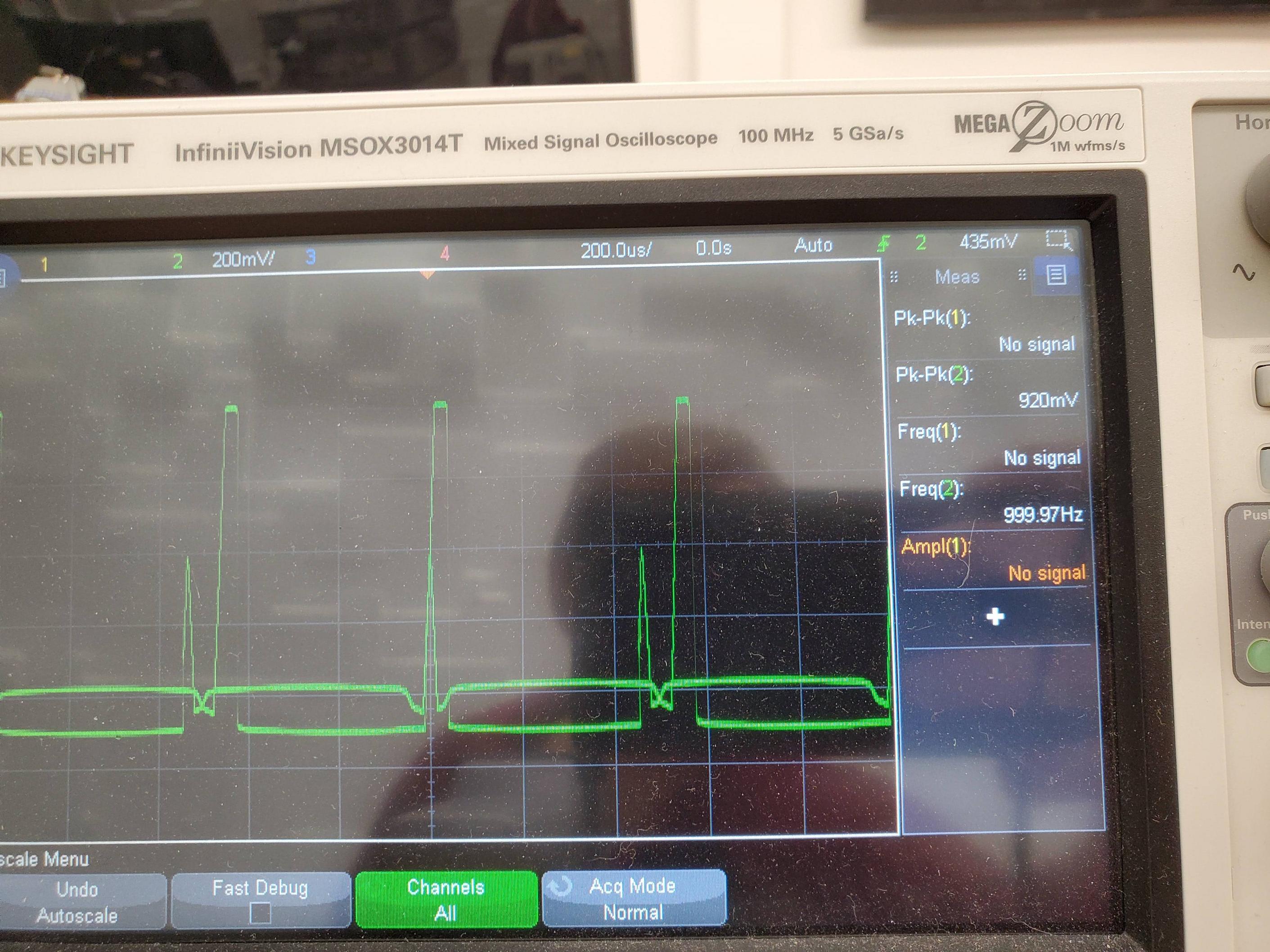
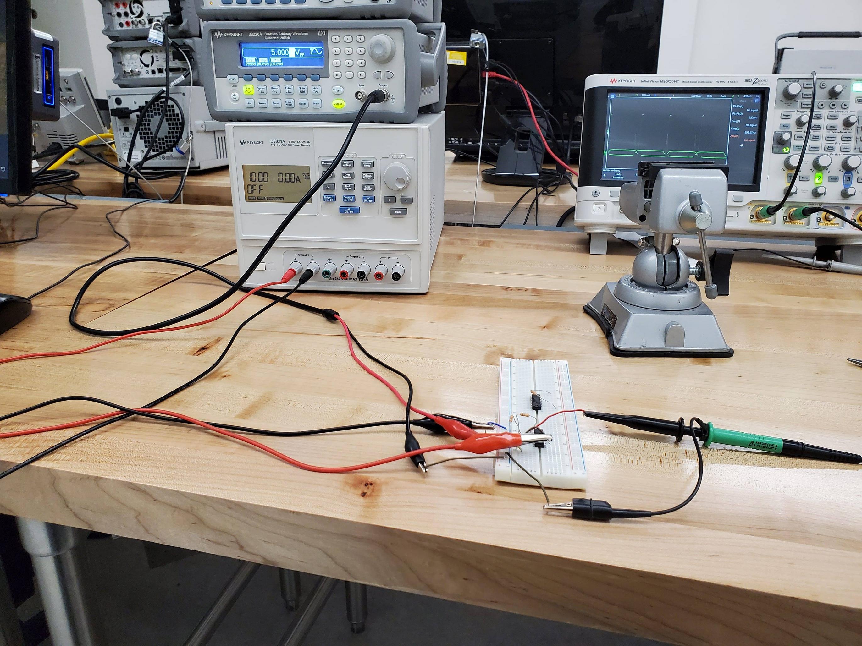
I built the circuit and I am seeing much less gain (in some cases negative gain), and extreme clipping.

Is there something I'm doing wrong here? It's super confusing to me that it would work so well in simulation and then not at all in measurement.

enter image description here

enter image description here

enter image description here

\$\endgroup\$
3
  • 5
    \$\begingroup\$ Since you've built an inverting amp with a gain of -10, what output do you expect if your input is +5V? How about if your input is -5V? Now, consider that your amp is supplied by a single 10V rail ... how does this fit in with your expected outputs? \$\endgroup\$
    – brhans
    Commented Dec 29, 2020 at 20:31
  • 5
    \$\begingroup\$ How on earth do you expect to get 49V out (per that sim) with a 10V supply? The sim is misleading you. \$\endgroup\$
    – user16324
    Commented Dec 29, 2020 at 22:18
  • \$\begingroup\$ The scope trace indicates that you’re operating at 40kHz; many audio frequency op amps will struggle with that. You need to consider the device’s bandwidth and for large signals the slew rate. \$\endgroup\$
    – Frog
    Commented Sep 9, 2022 at 20:49

4 Answers 4

6
\$\begingroup\$

I don't know what model the simulation software uses for the 3288RT op-amp, but it is ignoring the supply rails; you can't get a sine wave that gets to -50 V and +50 V when the power supply rails are only 0 V and 10 V, so the simulation is wrong.

If you want to get the sine wave you see in the simulation on your breadboard, you would need a dual ±50 V voltage supply for the op-amp, assuming it can do rail-to-rail.

I don't know what "real" op-amp you are using on your breadboard (an LM324, maybe?), but there aren't that many around that will work at those voltages, so better not try it without checking. The LM324 will only take ±16 V max.

\$\endgroup\$
3
\$\begingroup\$

That is an inverting amplifier. The way it is connected, it needs both positive and negative supply voltages to work. As it is now, the output cannot go to negative, which is needed to amplify the positive half of the input waveform.

\$\endgroup\$
1
\$\begingroup\$

The photo shows an opamp that is probably an LM324. Its input is plus and minus 5V and since the opamp has no negative supply then its input is destroyed by the negative parts of the input signal. The datasheet says Absolute Maximum input= -0.3V.

\$\endgroup\$
1
\$\begingroup\$

This is what the inverting opamp does: inverting opamp

\$\endgroup\$

Your Answer

By clicking “Post Your Answer”, you agree to our terms of service and acknowledge you have read our privacy policy.

Not the answer you're looking for? Browse other questions tagged or ask your own question.