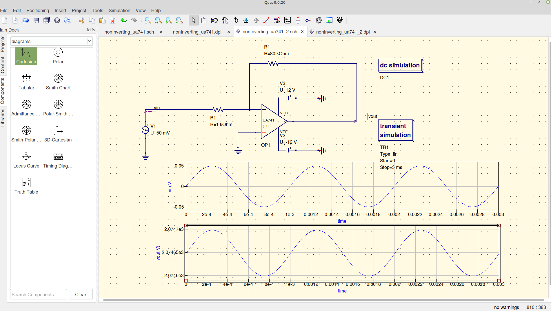
According with instructions provided here https://www.youtube.com/watch?v=dBY1k5qK2w4 (in Spanish), I tried to simulate an inverting opamp configuration, but I couldn't figure out the right vout behavior, as reported in the second graph of the following figure.
Output results with a high DC term which is not supposed to be in the YouTube video, nor in the well known theory. Furthermore I expect an out of phase behavior of the output signal, as compared to the input one.
Is there anyone who could find out what's wrong here?
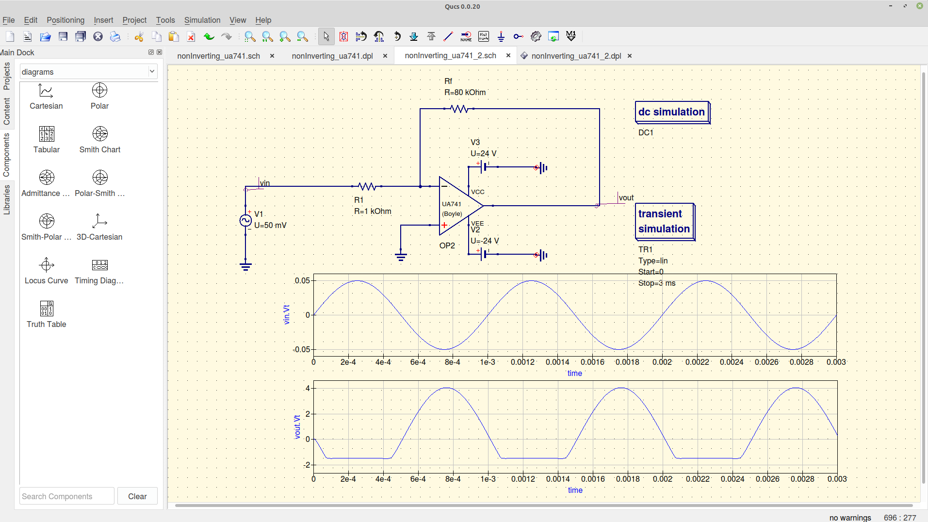
I did a second attempt . By the way, changing the opamp I've got this
That could mean the 741-opamp (TI) simulation software is not properly working on my QUCS.
With this other opamp the simulator seems to work reasonably well, but still there is an issue: I don't understand why there is a downward saturation on the output signal.


