0
\$\begingroup\$

Iv been contemplating which approach for voltage suppression for a 24V system.

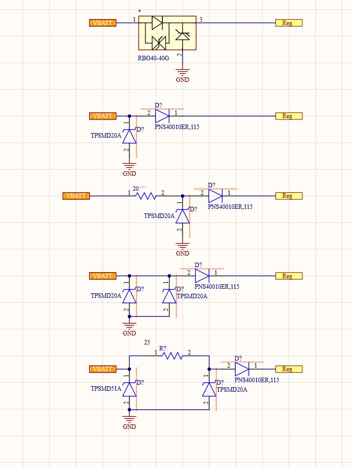
the parts in consideration are RBO40-40G// TPSMD20A || TPSMD251A// PNS40010ER,115

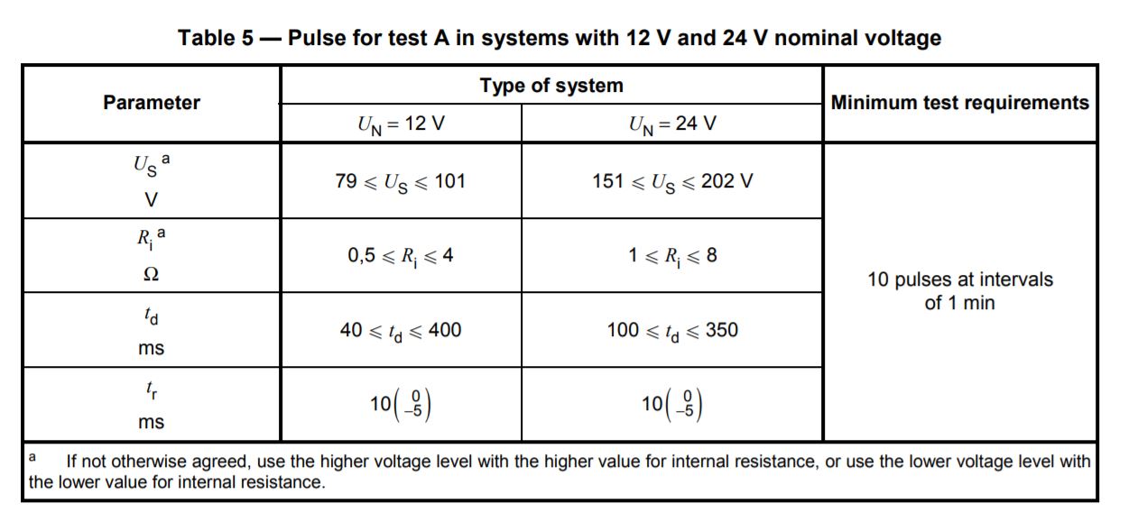
Load Dump load dump specs

for the one on the top reading the sheet kinda implies its more towards a 12v systems so iv ruled it out.

the second one, is my original attempt. im unsure if it needs a resistor with the max pulse current of 84A since the expected values at the input are between 151-202V, or i could have 2 in parallel like the following 2 circuits.

the final one is one that i had seen mentioned on VISHAY documents else where they have a beefy tvs at the start to drop it down to say 80 volts and have the other trim it down further which id assume would work alot nicer at a higher cost and less space.

another alternative i thought might be to use a surge suppressor IC from Analog LTC4366 which would be a little more dear than the other options ive presented.

Suppression circuits

\$\endgroup\$
8
  • \$\begingroup\$ also to note, if i were to add the 20 olms resistor would picking a surge resistor be enough for it to not blow up in the case of a load dump ? \$\endgroup\$ Commented Jan 4, 2021 at 23:45
  • 1
    \$\begingroup\$ With a reverse-protection series diode (a must if your 24V system is field wired), you might want a TVS on both the "inside" and the "outside" of the series diode. The series diode can rectify an oscillating surge. If there is enough capacitance on the inside to absorb it, it might not matter, but easier to just add it. Also the TVS on the "outside" of the series diode should be bidirectional, in case some fool like me hooks up the power backwards. \$\endgroup\$
    – Pete W
    Commented Jan 4, 2021 at 23:52
  • \$\begingroup\$ thanks for the tip ! if you dont mind, with regards to m.littelfuse.com/~/media/electronics/application_notes/… page 4 where they specify the ISO tests done on both 12/24 systems is that just the tvs alone ? i would guess my absolute best bet without reverse protection would be SLD8S24A since most regulators max out at 40 input m.littelfuse.com/~/media/electronics/datasheets/tvs_diodes/… \$\endgroup\$ Commented Jan 5, 2021 at 0:42
  • 1
    \$\begingroup\$ I am not experienced enough to answer that. What I said comes from 24V industrial stuff that I got thrown into as a component vendor. It's all field wired, everything is unique, the prints the integrators give to the electricians are full of mistakes, hence the paranoia. As far as the tests are concerned, the relevant standards will describe the test circuit. My guess would be the same as yours. \$\endgroup\$
    – Pete W
    Commented Jan 5, 2021 at 0:53
  • \$\begingroup\$ Regarding the SLD8S24A ... The min Vbr is 26.7V ... that is just a hair above the upper range of a "standard" 24V of +/-10%. I don't know what the automotive tolerance is. It feel like it might be cutting it too close. \$\endgroup\$
    – Pete W
    Commented Jan 5, 2021 at 0:55

0

Your Answer

By clicking “Post Your Answer”, you agree to our terms of service and acknowledge you have read our privacy policy.