1
\$\begingroup\$

My plan is to use an ADS1115 ADC to read a low impedance 0-5V output signal from a level transducer. The ADC data sheet gives guidance for ADC input filtering. This data sheet, and even other input filter design notes all assume a relatively high frequency input signal (High frequency relative to my application).

My application is a level transducer that will mostly be 0v for the majority of its life. I will only be monitoring the input signal for a high level event. If a high water level were to occur, it would happen very slowly, it would take over 10 minutes just for the level to increase an inch. Once the level reaches a high threshold; however, level reading accuracy is critical.

My design is power critical, runs on battery. I chose my sampling rate to be 64 samples per second. The entire system will wake from sleep, take a few samples, average them, and go back to sleep (sleep duration will be a few seconds). The transducer is mounted directly onto PCB via one or two inches of wire. Industrial environment, very noisy environment as wel.

Given this application, is a RC circuit really necessary? I would imagine just removing the resistor from the RC circuit and letting just capacitor filter all AC noise would be enough for my application? I would of course still use the differential capacitor as per the data sheet. Or would it be better to make a RC filter with a very low cut off? That was my original plan, but the use of precision resistors and required class 1 caps would eat into board space and allotted budget; I didn't want to go this route unless it would be necessary.

Thank you for taking the time to read!

\$\endgroup\$
16
  • \$\begingroup\$ Cut and paste the circuit you are talking about. You can embed images. \$\endgroup\$
    – Andy aka
    Commented Jan 13, 2021 at 17:10
  • \$\begingroup\$ why would you need precision resistors (as opposed to normal resistors) or class 1 capacitors? \$\endgroup\$
    – BeB00
    Commented Jan 13, 2021 at 17:13
  • \$\begingroup\$ What is the source driving the ADC inputs? Remember that they have finite input impedance. As for cost of an SMD capacitor, is that really important if you're using a several dollar ADC chip? Seems like cost optimization might be better focused elsewhere. \$\endgroup\$ Commented Jan 13, 2021 at 17:23
  • 1
    \$\begingroup\$ You can expect lots of rework/scrap with no design specs \$\endgroup\$
    – D.A.S.
    Commented Jan 13, 2021 at 17:33
  • 1
    \$\begingroup\$ @dandavis that's multiple orders of magnitude too high a cutoff frequency. Also, the argument "it's easy to add later" doesn't really work – the opposite is true: easier to omit later on; adding it implies a board re-spin. \$\endgroup\$ Commented Jan 13, 2021 at 20:29

3 Answers 3

5
\$\begingroup\$

An anti aliasing filter should be always present. It would be better to sample at high sample rate, use a FIR filter to eliminate the environment noise 50/60Hz, thus the anti-alias filter can be a small RC with low TAU value. Sampling at 64sps would imply large RC filter and it is very close to 60Hz, so most probably you will pick lots of noise/garbage.

See this example:

Youtube , source PDF

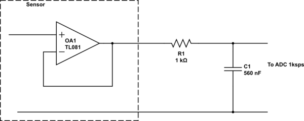
You could use 1kHz sampling rate with a 300Hz cutt-off anti-alias RC filter. $$f_{cuttoff}=\frac{1}{2\pi RC}$$

You said, your source has low impedance, so you don't need a buffer. Let we neglect the source impedance (=0) and we calculate as the entire resistance is the filter resistance R=1kOhm.

$$C=\frac{1}{2\pi Rf_{cuttoff}}=\frac{1}{2\pi\cdot 1k\Omega\cdot 300Hz}\approx 5.3\cdot 10^{-7}F\approx 0.56\mu F$$

schematic

simulate this circuit – Schematic created using CircuitLab

Above it is an anti-alias filter 300Hz cutt-off. Then you sample and filter with low pass FIR filter, for example 128 taps. You would get a precise measurement without environment noise.

\$\endgroup\$
1
  • \$\begingroup\$ How do I implement a FIR filter to eliminate the environment noise 50/60Hz? I am using also an ADC1115. \$\endgroup\$
    – bardulia
    Commented Jul 25, 2022 at 11:05
3
\$\begingroup\$

Your sampling frequency is 64 Hz. You need an anti-aliasing filter that cuts off much before that. That is just basic Analog Design. Even if there is no other source of noise, there could possibly be lighning off in the distance or ESD close at hand. I suggest 2200 Ohms and 10uF. This will give you a cutoff frequency of around 7 Hz. A 10uF ceramic capacitor is not too large physically. The 2200 Ohm resistor could possibly add some tiny DC error to your ADC reading, but you can calibrate it out (which you will probably have to do anyway). If it does lead to error and you don't want to calibrate you can consider a smaller R and bigger C or bite the bullet and buffer the signal, then filter it (so you will only have offset error which can be uV if you choose an appropriate buffer).

At the minimum, though, I would design the PCB with a place to put a 10uF cap next to the ADC and an 0402 or 0603 resistor in series. Because I have been down this road before. It is much better to have a place to put the components and not need them than to need them and have no place to put them. The cost of a small SMT resistor is totally insignificant, even in high volume production. The space is pretty small, too. It seems that you are at peace with adding a capacitor, which makes your reticence concerning the tiny cheap resistor very perplexing to me. Remember that the filtering is a function of the product of R and C. Adding an R greater than zero means your capacitor can be smaller.

\$\endgroup\$
2
  • \$\begingroup\$ Thanks for your answer! The data sheet says that R in RC needs to be below 1K and cutoff needs to be atleast 10x sampling frequency. I have decided to increase the sampling frequency in order to use smaller RC. \$\endgroup\$
    – James Pie
    Commented Jan 15, 2021 at 0:18
  • \$\begingroup\$ I saw that in the datasheet. The wording is a bit off. The sampling frequency should be 10x the cutoff frequency of the filter. Or, the cutoff frequency of the filter should be sampling frequency/10. I think sampling faster and using a higher frequency cutoff is a very sound idea. \$\endgroup\$
    – user57037
    Commented Jan 15, 2021 at 2:19
1
\$\begingroup\$

My design is power critical, runs on battery. I chose my sampling rate to be 64 samples per second. The entire system will wake from sleep, take a few samples, average them, and go back to sleep (sleep duration will be a few seconds).

At 64 S/s you can actually go back to sleep between samples.

Also, the power consumption of filtering and ADC combined will be low compared to the power used for your I²C bus'es pull-ups, just saying.

Given this application, is a RC circuit really necessary?

Yes.

Think of an RC filter as simple voltage divider, just that the "lower" resistor is a capacitor. Since a capacitor has a lower effective resistance for higher frequency, that makes it a frequency-dependent voltage divider.

Without the "upper" resistor, no voltage drop will be seen.

Why on earth would you want to save a resistor? That's literally the easiest, safest, most accurate and cheapest type of part you can get.

So, yes, without the R you don't get a filter.

Or would it be better to make a RC filter with a very low cut off?

"Very low" is a very relative term.

The theory is clear: Whatever input signal above 32 Hz reaches your ADC will get aliased into your signal of interest. So. Know where your signal of interest "ends" (i.e. its highest frequency component). You want to put your cut-off as closely as possible above that; the further above the cut-off frequency unwanted signal components are, the better they are suppressed.

Notice that a single stage of RC filtering isn't always sufficient. You need to start with a drawing of your spectrum to know what kind of filter oyu need.

hat was my original plan, but the use of precision resistors and required class 1 caps would eat into board space and allotted budge

Nothing says you need precision resistors. Standard 1% would totally do, since you never ever get capacitors even in the same order of magnitude of precision as you can get resistors! And you were about to hand-wavy omit the resistor, so I don't think you've actually calculated which accuracy you need.

The current going into your ADC is going to be << 1 µA (see the datasheet's input impedance table). So, the power lost in your resistor will be absolutely negligible – you'll want a large resistor value, anyway, to achieve a low cutoff frequency with a reasonably small capacitor.

So, go with the smallest 1% precision resistor you can solder. You can buy these down to 01005, at every distributor. They are narrower than your ADC's pins are wide. A resistor is not your space problem!

\$\endgroup\$
6
  • \$\begingroup\$ I was more so concerned with cost and space. The design is compact and housing was developed before all circuit revisions were done unfortunately. Yes, I think of a RC filter as a voltage divider dependent on frequency, but as I said, my signal is literally 0Hz. If it takes 10 minutes for my level to rise one inch, any voltage changes during a few millisecond sample will be meaningless, just noise. Therefore any AC signal during measurement, I'd want to ground. A cap on the input will take AC signal to ground depending upon the AC frequency, correct? What am I misunderstanding? \$\endgroup\$
    – James Pie
    Commented Jan 13, 2021 at 18:39
  • \$\begingroup\$ Much to unpack: no, your signal is not 0 Hz. If it truly were, you need never sample it, because it wouldn't ever change. You sample it 64 times a second, so I presume you're doing that because it might change. Define your signal's useful bandwidth, instead of claiming it had none, which is impossible. \$\endgroup\$ Commented Jan 13, 2021 at 18:48
  • \$\begingroup\$ Again, I don't understand how you can assume a capacitor without series resistor would filter. It would simply not. The cutoff frequency of an RC lowpass gets lower the larger the R is. With an R=0Ω=no resistor, you don't get a cutoff at all, it lets through everything. How is that suprising if you understand voltage dividers? \$\endgroup\$ Commented Jan 13, 2021 at 18:49
  • \$\begingroup\$ I understand that, by definition, a single capacitor doesn't filter, but doesn't it have some type of filtering effects? Let me give you the example that is in my head which is causing my confusion. If you have output voltage ripple on a power supply, you add capacitors on the output to decrease your peak to peak voltage. \$\endgroup\$
    – James Pie
    Commented Jan 13, 2021 at 23:27
  • 1
    \$\begingroup\$ Even though I think you should add an RC, the truth is that the capacitor will change the signal, even without an R. But that is only because there is some kind of random inductance and resistance in series with the noise sources (whatever they are). But I can't believe how much fight you are putting up on this. Put in a damn 0603 or 0402 series resistor. Start with zero Ohms if you are unconvinced. Then if you need to save the day later by changing it to 100 or 1k or 10k or 100k, you can. \$\endgroup\$
    – user57037
    Commented Jan 14, 2021 at 4:24

Your Answer

By clicking “Post Your Answer”, you agree to our terms of service and acknowledge you have read our privacy policy.

Not the answer you're looking for? Browse other questions tagged or ask your own question.