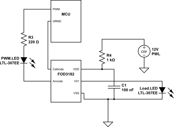
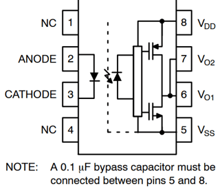
So this is the Optocoupler I will be using:
https://html.alldatasheet.com/html-pdf/505064/FAIRCHILD/FOD3182/978/2/FOD3182.html
My question is with the schematic of the data-sheet. Using Ni-multisim I can't find any components that have a similar internal schematic, and it looks like most are just some sort of photo-diode connected to a transistor, but their internal schematics are significantly different.
I have another post called "Driving Power MOSFET with Optocoupler Problems (Component FOD3182)".
I guess with this post I'd like to ask if anyone can clarify or expand on what kind of optocoupler this is? And I'm wondering what Rail-to-Rail means and if I am just underpowering this device on the isolation side?
The purpose of this circuit is to make sure the PWM signal is passing through the Opto. I don't have access to test equipment so the way I am doing this is by modulating the intensity of the LEDs.
The program I'm running will incrementally increase and decrease the duty cycle of the PWM signal to make the LEDs on both sides of the coupler increase and decrease intensity at the same ratios, allowing me to visually check that it is working correctly.
I do have a basic multi-meter but the coupler does not seem to be blocking the voltage from the supply at all, and is not modulating the intensity of the isolation side LED.
I know it's not a defective product as I have 12 and this is happening with each one I use.
Once I get this working I'm wanting to use it this to drive some power Mosfets instead of the LED, so I can drive a sensored BLDC motor.
I'm also a bit new to this site, so any pointers or tips of any sort regarding my problem or Stack Exchange in general are welcome.

simulate this circuit – Schematic created using CircuitLab

