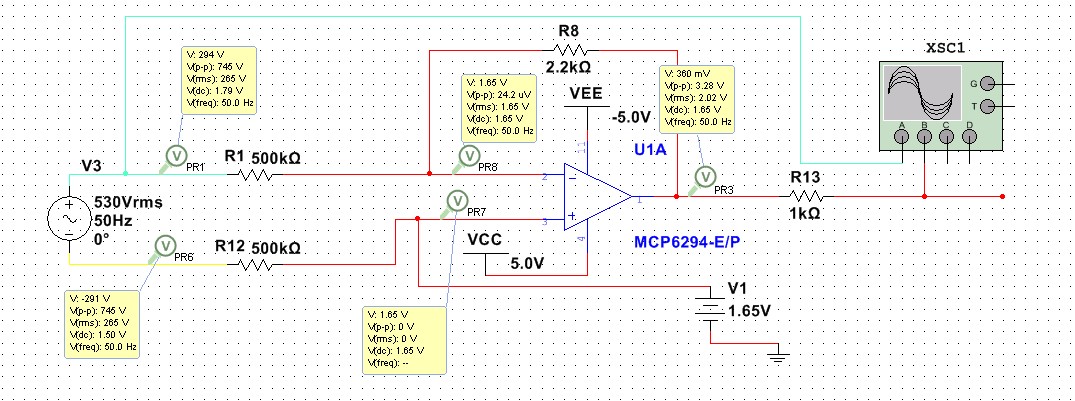
When I analyse this circuit to understand it's working, I got stuck at one point. Have a look on this circuit. When the feedback resistor value is 2.2k as shown in fig, I got the expected output with the DC offset at the output pin. There is some nA of current flow at the inverting input pin of this Op-Amp. There is only 3mVrms voltage at the inverting input.
When I increase the feedback resistor to 100k, the gain also get increased. I understood. Due to that, output signal also get clipped since the voltage swing is limited to 5V at the positive and negative side.
The intriguing part is the inverting input of the op amp. After increased the gain to 100k, significant amount of current up to some micro Amps of current starts to flow. This causes around 3.3 Vrms drop at the inverting input side.
The question is, why current flow increases at the inverting input pin after increases the gain of the op amp via feedback resistor. What happens there?
Also, I could not bring the voltage drop of 3Vrms at the inverting input via calculation.
Kindly help me to understand!!!

