0
\$\begingroup\$

I designed a PCB with STM32F411RE and a couple of sensors.

Before and after mounting components on the PCB, I checked the Vcc and GND pins for short circuit and I did not see any problem.

I am using SWD programming and I connected my ST-Link V2 to my board and successfully loaded the program.

Everything was normal for a few minutes. Approximately 3-5 minutes after, the MCU disconnected from the PC and then I checked the Vcc and GND pins and observed a short circuit.

Interestingly, as time goes the resistance between Vcc and GND pin increases by itself.

After that, I just mounted STM32F411RE, reset pin configuration and Vcap. I connected my board to PC and loaded the program successfully.

After a while the power pins shorted again. I just uploaded a simple LED blinking test program.

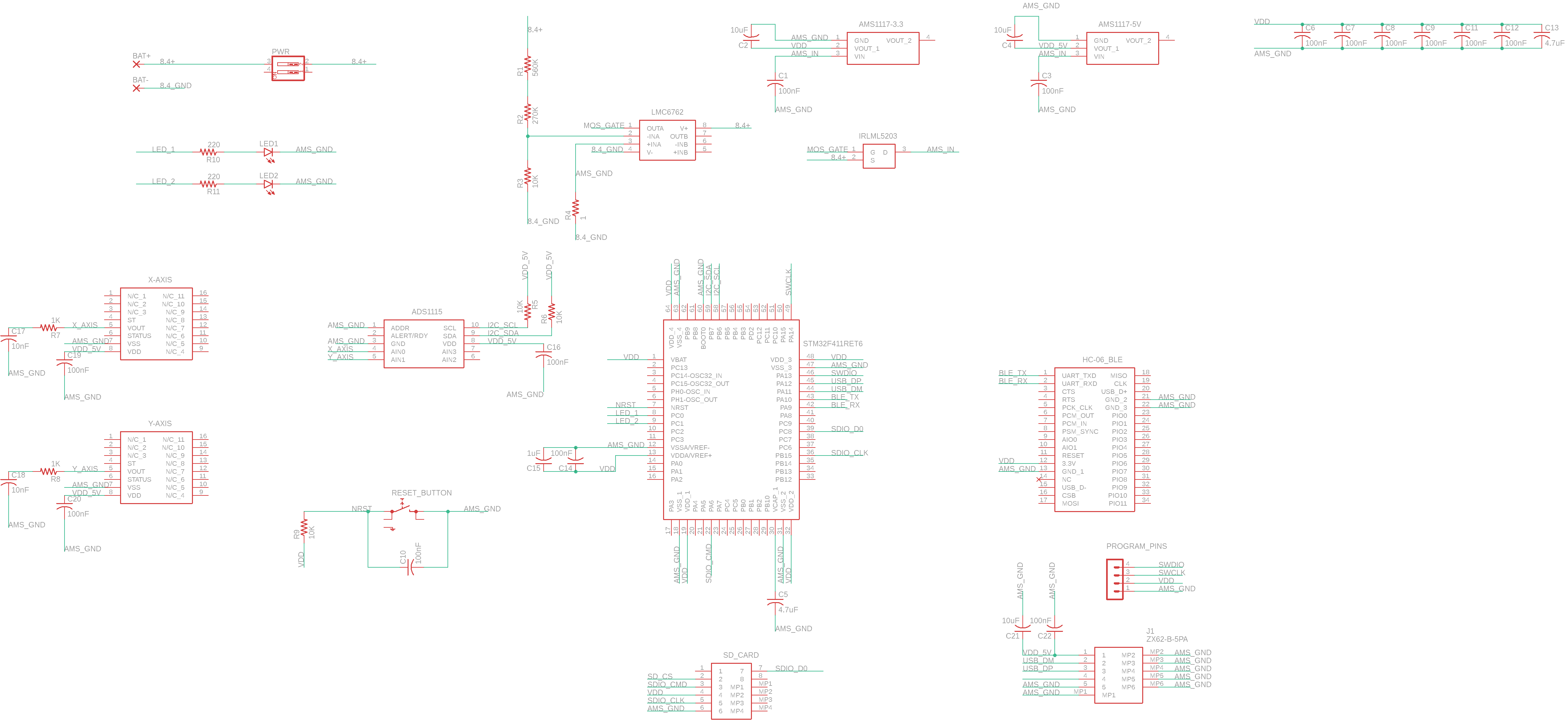
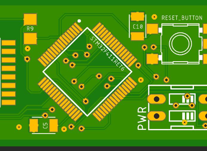
My board schematic and PCB images are below. Please help me to find my mistake.

enter image description here

enter image description here

\$\endgroup\$
14
  • 1
    \$\begingroup\$ The responsible component is probably getting very hot. Can you somehow discern where the heat is coming from? \$\endgroup\$
    – user57037
    Commented Jan 23, 2021 at 8:36
  • \$\begingroup\$ MCU is heating after a while but not too much, I observed that MCU is consuming 250mA after shorting. However according to datasheet, connection of MCU is correct, I am really stuck in. \$\endgroup\$
    – can
    Commented Jan 23, 2021 at 10:17
  • 1
    \$\begingroup\$ Well, 250mA at 3.3 (or 5?) Volts is a lot. Something must be getting hot. Check the two AMS regulators. Double-check that the pinout in the schematic symbols matches the pinout in layout. I don't like the fact that you have different grounds. But I am not sure if that is anything to do with your problem. It sounds like the fault is happening through silicon (not bare boards). One thing you can do is power the 3.3V rail with a bench supply and leave all the regulators out to see if that makes any difference. \$\endgroup\$
    – user57037
    Commented Jan 23, 2021 at 17:18
  • \$\begingroup\$ In second experiment, I mounted only STM32F411RE, reset pin configuration and Vcap on an empty PCB and same thing happened again, after a while power pins are shorted. I supplied 3.3V from ST-Link V2. In second experiment I did not use any voltage regulator. Is there anything wrong with the power supply of MCU?? I checked from datasheet and did not see anything wrong. \$\endgroup\$
    – can
    Commented Jan 23, 2021 at 17:56
  • \$\begingroup\$ I also checked that schematic and pinout in layout matches. \$\endgroup\$
    – can
    Commented Jan 23, 2021 at 17:59

4 Answers 4

2
\$\begingroup\$

First off: that is a terrible schematic; no ground or power symbols, no logical "flow", arbitrary boxes for things like the FET... the layout fragment looks good but you should spend some time working on improving your schematics because it takes considerable time to try to decipher them -- both us and you.

Moving on: one thing I notice right away is that your MCU is running off of 3.3V while your sensors are running off of 5V; this is going to cause trouble and it could be taking time for the regulators to finally punk out on thermal cut-off as they "fight" with each other through the sensors and MCU.

You've been asked by several people if anything is getting hot; something should clearly be getting quite warm, and my suspicion is going to be the regulators. A good rule of thumb is that if you can hold your finger/hand on the part, it's under 40C; if you're not particularly heat sensitive the part could be as hot as 50C.

I feel that you are not giving us all of the information. Take your time and methodically work the problem. When the board is cold, the system works. After a while, it stops and you keep mentioning that the rails are shorted. I'm willing to bet that nothing is shorted and the output is simply 0V. Feel around. Something will be getting hot. Probe around; watch the 8V, 5V and 3.3V rails -- something is going to move -- either suddenly or gradually. Put LEDs with appropriate resistors on the 8V, 5V and 3.3V rails -- what do they do, do they suddenly go out, or do they slowly dim?

Like Sherlock Holmes says: "Data, data, data; I cannot make bricks without clay!"

\$\endgroup\$
7
  • \$\begingroup\$ Thak you @akohlsmith for your detailed answer. Let me explain my last experiments on the PCB. For a second PCB I just mounted STM32F411RE, C5(Vcap), R9, C10, LED2, R11 and reset button. I did not solder any sensor, any voltage regulator etc. on second PCB. I used the power lines from ST-Link. I supplied only 3.3V to PCB. At the beginning I connected PCB via SWD to my computer and loaded simple LED blink program and everything works fine for a couple of minutes. After that I lost connection with PCB via ST-Link. I removed the power pins and see the short circuit. \$\endgroup\$
    – can
    Commented Jan 25, 2021 at 6:46
  • \$\begingroup\$ LED2 is connected to the PC2 GPIO output pin of the MCU there is also a 220ohm resistor. I think that the problem is in the microcontroller. Because in second experiment there is nothing than STM32 on the board. However, you are right I2C line should not be pulled up to 5V. In addition to that in second experiment where only STM32 on the board. The current consumption was normal it was about 10-20mA. \$\endgroup\$
    – can
    Commented Jan 25, 2021 at 6:48
  • \$\begingroup\$ I also want to ask that is flux possible to be conductive?? Because I am using a lot of flux and I couldn't clean most of them and my data lines and pins of MCU are very close. In addition to that my flux is not in a good condition. \$\endgroup\$
    – can
    Commented Jan 25, 2021 at 10:31
  • \$\begingroup\$ "see the short circuit" -- how are you measuring and concluding that it is a short? Please do not use the ohms or short circuit setting on your VOM to measure the supply rails; many meters supply voltages way too high (9V or even more sometimes) to get a more accurate resistance measurement and this can cause permanent latchup on sensitive devices such as microcontrollers. Your meter may be smarter, use low voltage or limit current to a safe level to prevent such damage, but until we know for sure, don't do it. \$\endgroup\$
    – akohlsmith
    Commented Jan 25, 2021 at 14:04
  • \$\begingroup\$ Flux can certainly be conductive, although it's rarely an issue with modern, good fluxes. However it's an easy fix. Use lots of isopropyl alcohol and a stiff nylon brush (an old toothbrush is fine). Rubbing alcohol has too much water - won't hurt anything but will take much longer to dry. I can get 99% iso from any pharmacy here and it's very inexpensive. \$\endgroup\$
    – akohlsmith
    Commented Jan 25, 2021 at 14:06
0
\$\begingroup\$

I could not solve the problem yet. I have reduced the solution to two different main distinction. I assume that internal voltage regulator shorts the power pins.

1- A physical interaction breaks the regulator. 2- Too much current is taken by internal units.

First one might be related with soldering issues. I saw some voltage regulator IC's that is broken after soldering with higher temperature and out voltage gets short to gnd.

Second one is only possible through SWD pins because only swd pins are connected to controller in my last setup.

I'm planning to measure the current difference between SWD connected setup and VCC-GND only setup but I dont have unused controller anymore I need to wait a few days.

If I can verify that power consuption is increasing dramatically after connecting SWD, we can say that we have a SWD interface design error.

I have tried a lot of stuff. Nothing else I have.

If you try something and get any kind of result please let me know.

Good luck.

\$\endgroup\$
1
  • \$\begingroup\$ Maybe the same things works for you too. Do not use flux, change the programmer ST-Link. If it work I will be happy. \$\endgroup\$
    – can
    Commented Jan 26, 2021 at 17:33
0
\$\begingroup\$

Probably I solved the problem finally. I removed the LEDs and did not use flux while soldering the STM32F411 and changed the ST-Link. As a result, the board is working fine, however I did not mount all of the components. For now, I mounted STM32F411, HC-06 Bluetooth and reset circuitry and it works without any problem.

I think that the problem may be caused by the LEDs or the ports that connected LEDs or maybe the ST-Link that I used is damaged or there is something. In addition to that I doubt that maybe particles (dirt) in the flux may changed the conductivity of the flux.

Tomorrow, I am going to complete the board.

I will give a feedback from here. Thank you everybody for your contribution.

\$\endgroup\$
3
  • \$\begingroup\$ I don't believe that you solved the problem. Your schematic is missing some key components like the decoupling of voltage regulators. You need to share the entire PCB, otherwise you're wasting your time and our time as well. \$\endgroup\$ Commented Jan 25, 2021 at 21:15
  • \$\begingroup\$ Believe or not, the board is working like a clock :) \$\endgroup\$
    – can
    Commented Jan 26, 2021 at 17:28
  • \$\begingroup\$ Yes, this is not "solved" - you have not determined why the boards failed, you've just changed a bunch of things until the problem no longer occurs, but have no conclusions to draw from your actions. Good luck with the rest of the design and bringup. \$\endgroup\$
    – akohlsmith
    Commented Jan 26, 2021 at 18:36
0
\$\begingroup\$

I don't believe that you have solved anything. The board is 99% to blame. It's not fixable, any physical boards you got can be tossed. Given everything else, it's likely that the MCU or some other part connected across power supply rails (like voltage regulator perhaps) fails due to electrical overstress caused by high inductances on the power supply circuits and voltages and/or currents beyond the limiting values. It's also possible that a regulator starts oscillating once it gets warm enough, and then runs away when it's presented with higher voltages it generated by pumping the L-C tank formed by all the long traces and the solitary capacitors stitching them here and there.

  1. The schematic is missing key decoupling components.

  2. You have not actually observed the behavior of the power supply rails - you have to look at each with a 100MHz digital oscilloscope (at least), using proper probing techniques.

  3. The 5V I2C bus is connected to a part with 3.3V I/O output swing (the MCU). This may not cause any damage, but is not how it should be done and you're cutting it close with margins for logic levels on the 5V side of it. In the ADS1115 datasheet, the \$V_{IH}\$ specification is given as 0.7VDD minimum. 0.75V = 3.5V. The MCU is not really driving 3.5V onto the I2C pins, thus you're using the A/D converter outside of its spec. Note that the 0.7*VDD does not refer to the voltage on the pull-up resistors, but to the supply voltage to the ADC itself - the ADC does not know nor care what voltage is on some resistors, all it cares about is what voltage results on the I2C pins. The pin protection diodes will shunt the pull-up voltage to MCU's VCC (3.3V), with a fairly small voltage drop since there'll be only about 100uA flowing into the MCU's pin when the levels are high. If you were to measure the high-level voltage on the SDA and SCK signals, it'd probably be right around 3.4-3.5V, either below spec or with no margin left. Even if it "works" now, it'll be reliability headache later. It's not causing damage, but if you get junk data from ADC (even occasionally), you'll know one reason why (your firmware may supply other reasons).

  4. It'll be very hard to see what other blunders are there on the PCB without you sharing all layers in full. From what I can see, there's no consideration given at all to the requirement of low impedance supply connections to the MCU. The supplies are routed as if they were some non-critical signals. Lots of potentially destructive ground bounce and VCC bounce is likely present. If some of the vias shown are meant to be ground plane stitching, then at least 3/4 of them are missing.

  5. There are zero decoupling capacitors visible in the vicinity of the CPU. Power supply and decoupling (e.g C5) is routed without regard for loop length. It's the loop that counts, after all - a circuit is literally a circuit. You have to be able to go round it with a finger tip or a tip of a pencil when someone asks - the layout must be, after all, driven by such considerations. For example, for C5, to investigate one should draw (red pen!) the path from pin 30, through the capacitor, to the ground plane (which seems to be on top), and then back to the related VSS pin (31) - it's unnecessarily long, and the capacitor looks like a fairly large package, too. But in that picture we should see either all of the decoupling capacitors, or direct vias to the capacitors mounted on the bottom layer directly underneath the VDD+GND pin pairs on the MCU. Those pins are paired for a reason: to minimize the loop length from chip's VDD ring through bond wires and lead frame and PCB to the capacitor, and back to the GND ring in the chip. Ideally, that loop should be <10mm long, on higher performance processors it'll be 5mm long or less.

Basically, the board is laid out mostly as if all copper was an ideal conductor and even more importantly, as if inductance was absent (even superconductors have inductance!).

\$\endgroup\$
1
  • \$\begingroup\$ you are in the issues of PCB design I need to work on it more. However STM32s are 5V I2C capable, you need to read this application note link pp.19 \$\endgroup\$
    – can
    Commented Jan 26, 2021 at 17:26

Your Answer

By clicking “Post Your Answer”, you agree to our terms of service and acknowledge you have read our privacy policy.

Not the answer you're looking for? Browse other questions tagged or ask your own question.