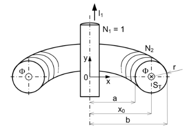
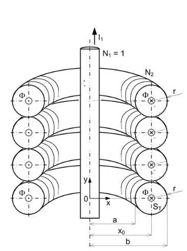
I'm planning on harvesting energy from a 33kV line which has an average 10rms A current. The main conductor (N1) has a overall diameter of about 13mm.In the beginning I tried to harvest around 3-4 W of energy but it seemed impractical with a core of 10^4 relative permeability and 1.8 T of flux density. To increase the harvesting energy we need to increase the core area (increasing r) while reducing the major diameter of the core (X0). So at some point it comes to a limit of energy harvesting as I understand. There's no possibility to put more than one turn of the primary conductor around the core and the average current of the primary conductor is limited to the above value 10rms A most of the time. Can you tell me is there anyway to harvest that much of energy from a current transformer for above specifications or do I have to reduce the expected harvesting energy amount. Does increasing the number of secondary turns (N2) increase the harvested energy amount. I went through the theories so many times but I still feel confused about this. I'm expecting a descriptive answer and I will provide all the details if you need prior answering the question.
-
1\$\begingroup\$ Wawawewa be very careful. Current transformers are very dangerous, as are 33kV lines. Current transformers are rarely used with anything but a specialized resistor load because even a small CT can fail in a spectacularly dangerous way. Also, what is the core you are referring to? CTs are usually coreless. \$\endgroup\$– K HCommented Jan 24, 2021 at 5:36
-
2\$\begingroup\$ A current transformer creates a current on the secondary directly proportional to the current on the secondary. It can produce ridiculously dangerous output voltages when presented with a significant output resistance or open circuit. How do you intend to ensure that your load operates and fails in a safe way? A CT is used mostly only as a way of measuring a more dangerous current, and typically only in a properly mounted and rated permanent installation. I would also note this appears more on the lines of energy theft than harvesting. \$\endgroup\$– K HCommented Jan 24, 2021 at 5:44
-
1\$\begingroup\$ You already have the answer to this in your previous question. N2 doesn't change the voltage drop that the core can impose on the line coming through. No voltage drop, no energy extracted. You need a big core, extractable power is proportional to core volume. Constant of proportionality depends on core material permeability up to a saturation limit. Try doing the sums with permaloy/mu-metal. \$\endgroup\$– Neil_UKCommented Jan 24, 2021 at 5:49
-
\$\begingroup\$ Oh yuck. Current on secondary is proportional to current on primary, not to itself. Horrible typo. \$\endgroup\$– K HCommented Jan 24, 2021 at 8:50
-
\$\begingroup\$ @KH what do you mean when you say this: CTs are usually coreless. \$\endgroup\$– Andy akaCommented Jan 24, 2021 at 10:01
3 Answers
A current transformer (CT) "projects" the secondary (burden) impedance to a very much lower impedance on the primary via the turns ratio squared. That impedance becomes parallel to the inherently low magnetization inductance that a CT will naturally have. For example: -
If the burden is 300 Ω and turns ratio is 1:100 then the burden appears as \$\frac{300}{100^2}\$ or 0.03 Ω.
So, the important thing you have to care about (in normal CT measurement applications) is that the burden impedance projected to the primary is significantly lower than the magnetization inductance impedance of the thick wire passing through the core. If you don't do this, you will get a measurement error but, in your application, you are less worried about that error.
However, any current flowing in the magnetization inductance, cannot be utilized in the secondary so, if the primary current is 10 amps, you probably want at least 9 amps to be flowing in the projected burden impedance and no more than 1 amp of it magnetizing the core.
with a core of 10^4 relative permeability
Here's where you start - you need to determine the magnetization inductance of the primary. You need to calculate this. I can make a guess that it is (say) 100 μH but that's just a guess.
However, once you have that inductance, you can calculate the reactance. I'm assuming 50 Hz and therefore 100 μH has a reactance of 31.4 mΩ. That's milliohms. So now, you want to ensure that your secondary burden projected to the primary is about 10% of that value (3.14 mΩ).
The power in the projected burden is 9 amps squared multiplied by 3.14 mΩ. That's 0.254 watts.
$$\boxed{\text{But remember I guessed that the primary inductance is 100 μH}}$$
If the magnetization inductance is 1 mH, then it has an impedance of 0.314 Ω at 50 Hz and then, your projected burden would be one tenth this value (31.4 mΩ) and take 9 amps. That's now a power of 2.54 watts. That power is realizable in the secondary circuit (with a resistance of 314 Ω).
$$\boxed{\text{It's all down to making the primary magnetization inductance as big as possible}}$$
It's got very little to do with the turns ratio. But, can you realistically make the primary inductance as high as 1 mH with 1 primary turn? Personally, I don't think it's practical but, maybe if you do the math you'll show how.
But you could really push things (at the risk of saturating the core) and assume that the projected burden resistance has the same impedance magnitude as the magnetization reactance - with the same magnitude you could argue that of the ten amps flowing in the primary, 7.071 amps flowed in the projected burden resistance and, to achieve say 3 watts, you'd need a resistance of 0.06 Ω and a magnetization reactance of the same.
That turns out to be a magnetization inductance of 191 μH. Maybe that's more realizable but, the devil will always be in the detail. Also don't forget that there will be potentially more core saturation due to 7.071 amps in the magnetization inductance. You do the math.
Does increasing the number of secondary turns (N2) increase the harvested energy amount.
In general, no. The more turns on the secondary, the higher the secondary voltage, but the lower the current. The amount of energy transferred to the secondary depends primarily upon the voltage drop of the primary (which for a CT is quite small) and the current through the primary. For a fixed frequency, and a fixed primary current, the voltage drop is limited by core saturation. If your core is not near saturation, you may increase the voltage drop by adding turns to the primary. However, if the core is near saturation, the only way to increase the voltage drop is to use a transformer with a different core. Changing materials can help, but eventually, the cross-sectional area of the core must be increased to allow more flux.
(The exception to the "no" answer arises from the fact that your load may not be well matched to the current transformer. If your transformer is inefficient because of load mismatch, adding turns to the secondary may help, or may make matters worse, depending upon whether the load impedance is too high or too low.
Increasing cross-sectional area of a torus with a fixed minor diameter means increasing the mid-diameter. The latter is something you want to avoid. However, you are not limited to a torus geometry. A "tube" geometry can have the same mid-diameter as a torus, but a significantly larger cross sectional area.
On the whole, "harvesting energy" with a current transformer seems expensive in terms of copper wire and core material. I don't know your situation, but it may also be dangerous, illegal, bad karma, or any combination of these.
-
\$\begingroup\$ Can you tell me a more practical method that could be used in such a situation.I would like to study. Doesn't matter if it can't be installed by an ordinary person, just looking for good solutions. \$\endgroup\$ Commented Jan 25, 2021 at 5:20


