0
\$\begingroup\$

I have a flyback regulator with some output ringing spike problems. It is a 70-130V input with 6V regulated output and 75V unregulated output based on the LM5021 flyback IC.

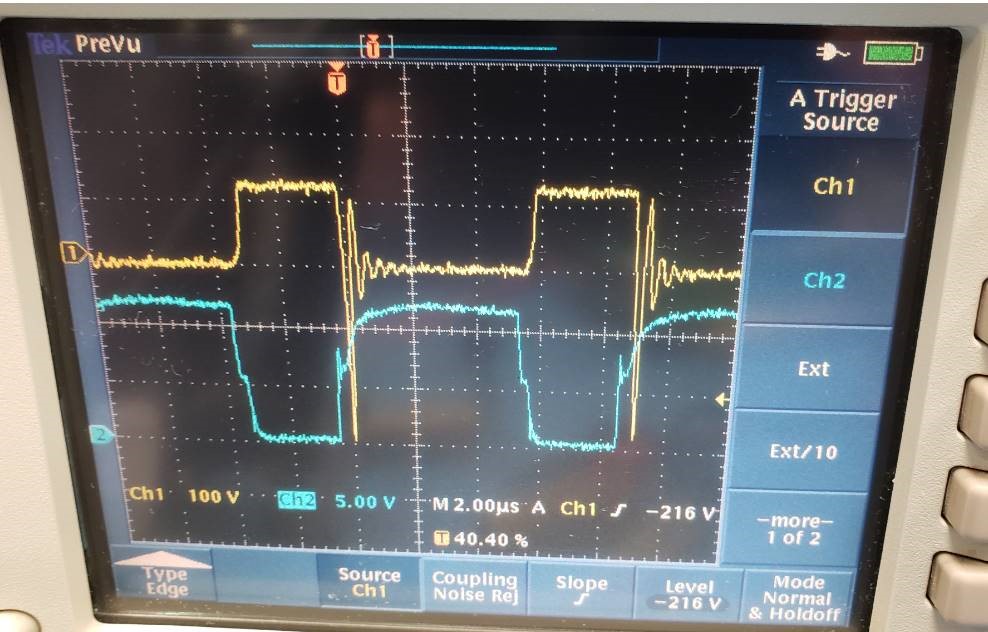
When going from no load to 3W load on the regulated 6V output, the transformer output pin on the 75V output (basically the voltage across the output rectifier) has a huge negative spike. The load transient momentarily causes the duty cycle to jump to about 70%. This negative spike only happens during transient load on the 6V. I haven't been able to test high load on both outputs yet so maybe it will happen there as well. Right now the spike is getting dangerously close to the limit of my 600V output rectifier.

The yellow trace is the voltage across the output rectifier and the blue trace is the gate drive of the switching FET. The transformer doesn't like being put back into charging state while in continuous mode it seems. I have since added 500pF with 200Ω across the output rectifier and it helped a little bit by getting rid of higher frequency ringing but not the main negative going spike.

enter image description here

Here is the output stage. The 6V feeds back to an opto feedback network. The 18V is used to self power the power supply. I measured about 16μH of leakage inductance in the transformer. It is meant to operate in continuous mode when up to 70W is drawn from the 75V output. When there is little to no load it will run DCM and do pulse skipping.

I would really love to figure out how to knock down that negative voltage transient. Maybe I should just go to a 1kV output diode. With 80V on the primary side (afraid to go to full 130V input yet) and 75V on the output I don't understand how I get 400V spikes across the output diode. Transformer step-down is 36:25 for the 75V output and 36:2 on the regulated 6V output.

Thanks for your help!

enter image description here

Here is a more complete representative schematic of this supply from my simulation file: enter image description here

\$\endgroup\$
5
  • \$\begingroup\$ Show the full schematic not some fractal. \$\endgroup\$
    – Andy aka
    Commented Jan 25, 2021 at 20:37
  • \$\begingroup\$ The choice of diode may be critical. Having the diode turn off too fast might be the cause. Try a diode with slower switching. It’s a common cause of EMC issues. I’ve also seen the use of ferrite beads on leaded diodes to address these issues. Other methods are snubbers across the diode (like you’ve tried) and across the winding. \$\endgroup\$
    – Kartman
    Commented Jan 25, 2021 at 21:15
  • \$\begingroup\$ Thanks for the feedback Kartman, the slower output diode is a good idea to try. This one is an ultrafast. Andy, the full schematic is several pages with lots of unrelated stuff and is proprietary so I can't post it all unfortunately. The power supply part is just an LM5021 into a UCC27322 gate drive into a 900V switching FET with standard TL431 reference feedback into an opto-isolator as seen in LM5021 reference designs. \$\endgroup\$
    – ucmikesb
    Commented Jan 25, 2021 at 22:57
  • \$\begingroup\$ You can use an RC snubber if nothing else works. You can google around with regards for how to size it. Typical method involves observing what the frequency of the ringing is and some paper napkin calculations to estimate what it is in the circuit that you need to dampen and acquire initial values for the components. Then proceed to fiddle with them. Or you can jump straight to the trial and error stage. \$\endgroup\$
    – DKNguyen
    Commented Jan 25, 2021 at 23:59
  • \$\begingroup\$ After further investigation it looks like the source of the negative going spike on the secondary is from the turn on spike in the primary. Transformer winding capacitances can cause a little current spike right at the beginning of the current ramp through the primary and this coincides perfectly with the negative going spike on the secondary. The strange thing is that I am using a transformer bobbin that is really two bobbins that clip together so there is good primary to secondary separation which should mean low capacitance. \$\endgroup\$
    – ucmikesb
    Commented Jan 26, 2021 at 22:13

0

Your Answer

By clicking “Post Your Answer”, you agree to our terms of service and acknowledge you have read our privacy policy.

Browse other questions tagged or ask your own question.