I am using a whole array of IXYS CPC7524 high-voltage switches in one of my designs. Although the design of this specific switch is not made explicit, its characteristics and other products in the IXYS product line (such as the CPC1511) leads me to believe that the pass elements are quite probably pass NMOS devices with additional thermal protection circuitry.
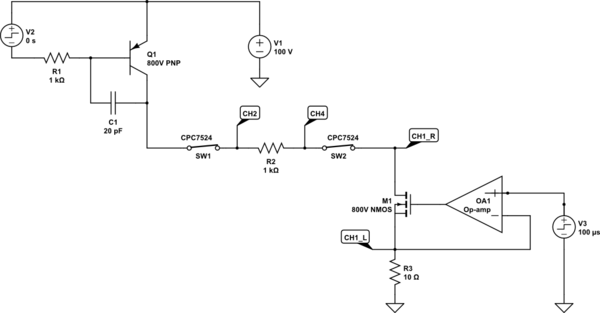
The application requires fast switching of voltage/current across the switches (which remain constantly turned on) and we are getting very problematic behavior out of them. This conceptual schematic shows how the switches are being used:

simulate this circuit – Schematic created using CircuitLab
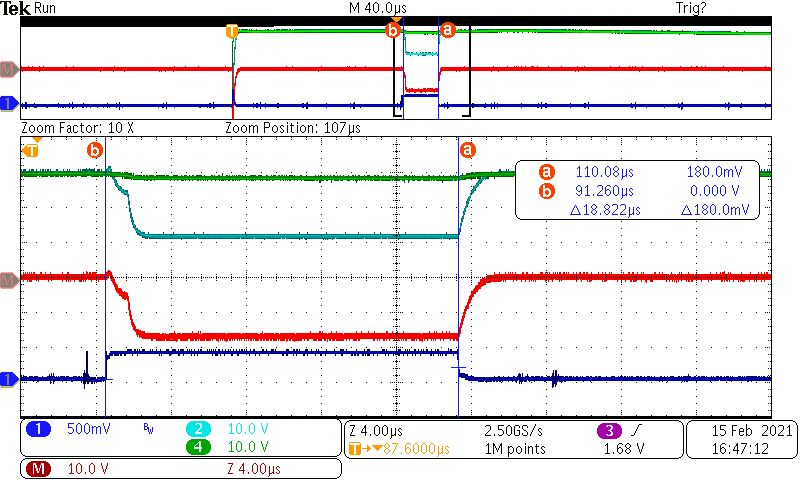
Q1 is used as a saturated switch and M1 as a current source. The slew rate in all nodes was measured and it never exceeds 100V/µs (the CPC7524 is specified in excess of 1500V/µs), however this is what we see on those nodes (everything is turned off after 600µs from the trigger):
Which clearly shows the switches enter a high-impedance state as soon as the NFET turns on, and takes as much as 250µs to reduce their impedance to the point the circuitry becomes properly biased (the chatter in the Drain node (CH1_R) shows instability due to the gain provided by the presence of the switch impedance).
In other scenarios (e.g., higher voltage or a shorter delay before NFET turn-on), the switches simply latch-up a temperature fault (an undocumented behavior) and open the circuitry requiring a power-cycle.
NOTE 1: this is a conceptual schematic. The details of the application are not very relevant. Suffice it to say that I need something that behaves just as a physical and slow mechanical switch or relay, connecting two sides of a circuit that has large fast-varying waveforms. Not a dynamically varying resistor, which is what I am getting with these switches.
NOTE 2: This is implemented in several interconnected PCBs with high-voltage edge-card connectors. We investigated all possibilities (including the possibility of inductive coupling between nearby traces) before narrowing down the problem to the switches. So yes, we are 100% certain the switches are the problem. And we understand the problem well enough to get the switches to predictably misbehave at will. The rest of the circuitry works exactly as designed.
Question
As these switches are clearly not acceptable for our application, before we undergo a redesign using large, cumbersome, and power hungry reed relays (note there are large numbers of these switches), does anyone know if a simpler Solid-State Relay, such as the Vishay VOR2142A8 would present the same kind of problems?
Can anyone suggest a better solution?


