4
\$\begingroup\$

In IEEE 802.3cg, a new (2019) 10BASE-T1S interface is defined. The intent is to deliver both power and 10 Mbps Ethernet data over a single conductor pair.

I understand 10BASE-T1S was designed to support a very simple PHY front-end implementation. Are there any example circuits to do this? Is it based on the same magnetics as other twisted-pair Ethernet, or is capacitive coupling used?

\$\endgroup\$
3
  • \$\begingroup\$ Not sure why you do not have access, since you posted this you have internet access. I simply used Google and entered this: 10BASE-T1S In the first 5 hits I found parts, IEEE specification, tutorials etc. When you go the the manufacturers that you find they will even give you example circuits and parts list, there's included of course. \$\endgroup\$
    – Gil
    Commented Jan 27, 2021 at 20:40
  • \$\begingroup\$ Thanks @gil, I was having some problems with the IEEE site, resolved now. \$\endgroup\$ Commented Jan 27, 2021 at 22:59
  • \$\begingroup\$ I find data sheets for parts implementing 10BASE-T1L, like TI DP83TD510E, but so far I haven't found 10BASE-T1S. @Gil, can you give me a for-example? I think many of the apparant search engine hits are really for 100BASE-T1. \$\endgroup\$ Commented Jan 27, 2021 at 23:59

2 Answers 2

3
\$\begingroup\$

Actual PHY front end circuits depend heavily on the application they will be used in. It is recommended to consult your PHY vendor for the front end circuits they recommend for a particular application.

IEEE 802.3cg requires all devices to tolerate (without damage) up to 60 V dc source limited to 2A across the medium-dependent interface (MDI) differential pair. It also specified a maximum of 15pF differential capacitance and a minimum 10kOhm differential resistance. When Power over Data Lines (PoDL) is implemented, there should be a minimum of 80uH differential inductance per node.

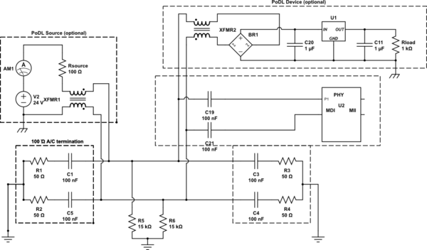
A minimum interface consists of two 100nF coupling capacitors, one on each leg of the differential pair. Each end of the segment (multidrop mixing and point-to-point) requires a 100Ohm differential termination resistance. Typically, the end termination resistance is implemented as two 50Ohm resistors in series with an AC coupling capacitor to ground between the resistors to provide a common mode termination. If you use PoDL, you will need capacitors to couple the termination to the differential pair to avoid the termination acting as a constant DC load.

Resistors no less than 5k (to meet the minimum 10k differential resistance requirement) from each leg of the differential pair to ground are often used between the AC coupling caps and the MDI to drain any charge that may build up on the differential pair. The actual values will often be much larger than 5k, but the lower limit may depend upon the PHY used.

For PoDL, one would use an inductor from each leg of the differential pair to power and ground. The size of the inductor must be small enough to not cause excessive droop on the data signal.

IEEE 802.3cg only defines power over a 10BASE-T1S point-to-point segment. Power is not defined for multidrop mixing segments, which is one advantage of this new technology. A new task force, 802.3da, is currently working to define power over single-pair multidrop mixing segments.

\$\endgroup\$
7
  • \$\begingroup\$ Thanks. This answer has a lot of additional information beyond what I asked for, it's a bit distracting. The part starting "A minimum interface consists of two 100nF coupling capacitors..." is at it's core the sort of thing I was looking for, but a diagram would be better than the text alone. \$\endgroup\$ Commented Jan 27, 2021 at 23:18
  • \$\begingroup\$ You'll also likely get more votes if you can source your information. \$\endgroup\$ Commented Jan 28, 2021 at 0:07
  • \$\begingroup\$ Source: IEEE 802.3cg-2019 and I was on the task force that worked on the spec \$\endgroup\$
    – TimB
    Commented Jan 28, 2021 at 0:23
  • \$\begingroup\$ Additional sources may be found on the following pages, but keep in mind that they are all developmental documents and may have changed in the final specification. grouper.ieee.org/groups/802/3/cg/public \$\endgroup\$
    – TimB
    Commented Jan 28, 2021 at 0:27
  • \$\begingroup\$ Thanks again @TimB. I've updated the Wikipedia article en.wikipedia.org/wiki/Ethernet_over_twisted-pair, trying to add IEEE 802.3cg-2019. But I'm no expert; perhaps you could contribute there too. \$\endgroup\$ Commented Jan 28, 2021 at 22:52
0
\$\begingroup\$

I'm trying to put @TimB's answer about a minimal implementation into a conceptual schematic. There is plenty of room for improvement, but here's what I understand so far...

schematic

simulate this circuit – Schematic created using CircuitLab

\$\endgroup\$
3
  • \$\begingroup\$ Tim wrote about putting in 5K+ resistors to drain and [sic] charge that may build up. Not sure where they go, or if I've got the cap values in a reasonable range. \$\endgroup\$ Commented Jan 29, 2021 at 3:10
  • \$\begingroup\$ That looks about right. I would put a 15k resistor to ground on the MDI side (left) of C19 and C21. Again, the actual front end circuit will depend on your application requirements. Also, Clause 104 does specify which pin of the MDI is positive and negative power I believe. \$\endgroup\$
    – TimB
    Commented Jan 29, 2021 at 6:07
  • \$\begingroup\$ Am I using the right "ground" symbols? Circuit Lab supports Earth, Chassis and Logical ground, is the distinction significant in this context? \$\endgroup\$ Commented Jan 29, 2021 at 6:41

Your Answer

By clicking “Post Your Answer”, you agree to our terms of service and acknowledge you have read our privacy policy.

Not the answer you're looking for? Browse other questions tagged or ask your own question.