I understand how Halbach arrays strengthen the magnetic field on one side of the array. I also know that, in a permanent magnet (PM) motor, there is already a limit on the air gap flux you can design for, as beyond a point, there is magnetic saturation in various parts of the stator steel. If you can achieve this flux using a regular array of strong magnets with high remanence, what is the point of the Halbach array? Are they only used for cheaper magnets to get to that near-saturation level of flux? Or is there something I am missing?
-
\$\begingroup\$ With a pair of Halbach array rotors, you can build a motor without the need of steel, making it light. But the magnets don't have a such mechanical strength to make a useful machine, so these arrays are more for fun, research, study. \$\endgroup\$– Marko BuršičCommented Jan 29, 2021 at 20:38
-
\$\begingroup\$ I just found out that Tesla is using this principle in its Model 3. The advantage being that the mass of the wheel (including the motor) can be lower than with another type of motor, making suspension less complicated. \$\endgroup\$– HarryHCommented Mar 4 at 10:49
3 Answers
If you can achieve this flux using a regular array of strong magnets with high remanence, what is the point of the Halbach array?
None, which is why you don't often see Halbach arrays used in motors.
Actually there is a case for Halbach arrays - when you don't have Back iron. In most motors the magnets are mounted on an iron or steel ring which performs the task of coupling flux between magnets. If for some reason you need to use a non-magnetic rotor material then Halbach arrangement may be necessary to get the desired flux.
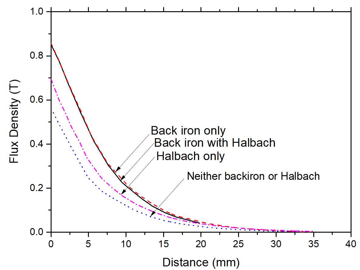
In the graph below we see the effect on flux of having Back iron, Halbach, both or none. In this example the Halbach array is better than a conventional magnet arrangement with no Back iron, but worse than a conventional arrangement with Back iron. If Back iron is present then Halbach provides no improvement.
Advantages and disadvantages of Halbach array in BLDC motor
The site above also mentions two other possible reasons to use Halbach arrays - to reduce eddy currents and cogging torque. But this can also be achieved with a conventional design. So why are Halbach arrays so often used in DIY designs? Probably because (as the article suggests) it avoids having to machine steel parts.
-
\$\begingroup\$ It appears the lines on your graph are mislabled. See the FEMM simulations in my answer for reference. My findings match this graph, except the top 2 lines are halbach with and without iron, showing only marginal improvement because there is little field on the back side. \$\endgroup\$– K HCommented Jan 30, 2021 at 8:00
-
\$\begingroup\$ @KH Nope. "Back iron only Torque output: 0.714 N.m... Halbach Only Torque output: 0.683 N.m" Note that these numbers apply to this simulation only, which uses equal thickness magnets. A Halbach array with thicker magnets may work better, but then you have a larger motor with a lot more magnet = not a fair comparison. \$\endgroup\$ Commented Jan 30, 2021 at 16:03
-
\$\begingroup\$ Oh I see they didn't use an optimal halbach array. Halbach poles are smaller than they should be, although they used more magnet mass for the halbach array. My tests assumed an optimal halbach array (width of pole=2x thickness) with an equal mass of magnet to compare. \$\endgroup\$– K HCommented Jan 31, 2021 at 0:29
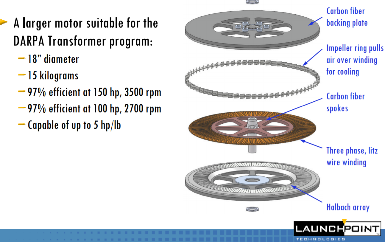
A Halbach array motor, no steel:
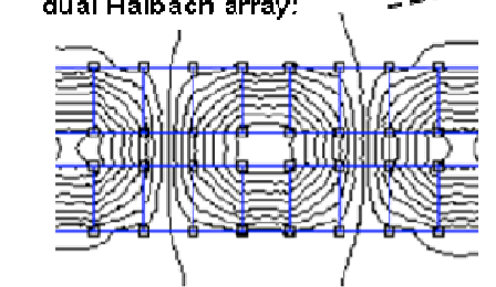
The shape of the magnetic field in the Halbach array is such that it can close its path if two rotors are used. In a classic motor, you have to use a ferromagnetic material both for rotor and stator to be able to close the magnetic path.
With only one Halbach rotor, you would still need a ferromagnetic stator, with two such rotors, even stator can be made coreless.
As you can see, the flux can have its complete path. In the pictrure there are two Halbach array rotors, in the mid part the stator is inserted.
At first look, it is a miracle of science, since it is lightweight compared to steel rotor and stator. The drawback is that magnets still need a support, could be a aluminium plate, carbon,...the stator also need a support, like epoxy resin. Without the metal parts also the heat dissipation is low, so it tends to overheat.
I've actually been analyzing the benefits of using a halbach array with a FEMM modelling tool recently, so you might be interested in my findings.
I've been using FEMM(Finite Element Magnetic Modeller) to analyse Halbach arrays because I want the best bang for my buck in my hobby motors, and halbach arrays are great, especially when you're building lightweight, can't machine your own iron cores, or where field strength per magnet cost is an issue for you. Air is harder to compress field into, but it doesn't saturate the way iron does.
Note that all the magnets in a halbach array try to push apart, so assembly is a big challenge, especially for larger magnets, and if you "Push" the fields of the magnets against eachother and move them too much during assembly(Goal is to smoothly put the magnet in place and never have it move again relative to neighbouring magnets) they can be partially demagnetized.
My experiments have been to establish the strongest possible magnetic field at the center of the pole face(Prime area because flux lines are perpendicular here, so I'll present some of my findings.
First, at least one complete magnetic circuit must be present for maximum field projection from the magnet, so I analysed the center two poles of a set of four poles modelled. All magnets are N40.
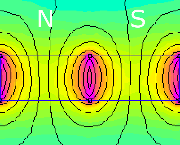
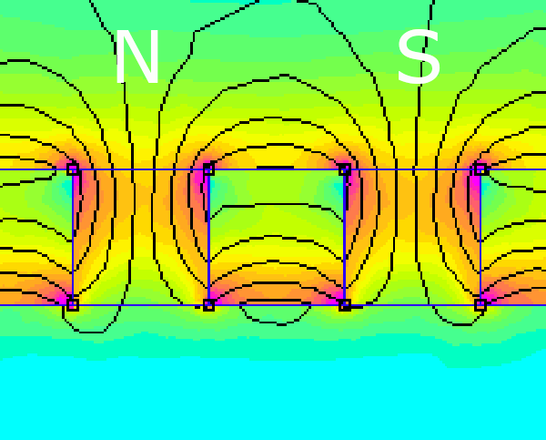
First a conventional pair of poles with no iron back.
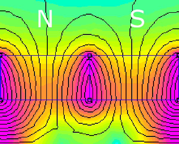
Next a conventional pair of poles with iron backing note the backing is as thick as the magnets and still almost saturated. Note that the strongest parts of the field are concentrated center between the poles where they do little good.
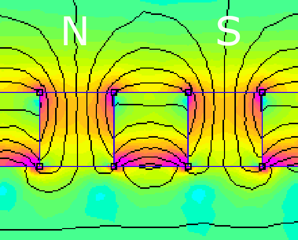
Now a pair of poles in a halbach arrangement using the same mass and strength of magnet: Note that in the halbach arrangement, not only is the overall field stronger, but the stronger parts of the field are moved closer to center pole face where they are more useful to a rotating machine.
Finally a pair of halbach poles with iron backing. Note how little of the iron is used and therefore how little would be required to contain the magnetic field in situations where that is an advantage.
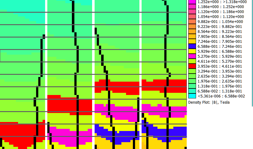
Finally because the most relevant for my project is field strength at a given distance, and center pole field strength matters most, I prepared a side by side comparison in the same order and re-colored several bands for illustration purposes. Horizontal lines are 1mm each from the face of the magnet. You can see that the normal magnets with no iron backing performed the worst. Adding an iron backing pushed the same field strength out twice as far, from 2 mm to 4mm by completing the magnetic circuit where possible. The halbach array, even with no iron back, because of the cancellation and short circuiting of the field on the bottom side and reinforcement of field on the top side, outperforms the iron backed array by 1.5mm and predictably sees only a tiny improvement when iron is added.
Note that thus far I've only evaluated back side iron and single sided arrays, but you can see from the simulation that the halbach array gives not only improved overall field strength and range, but has its field concentrated more usefully distributed compared to an equal mass of conventionally arranged magnets, with or without iron backing.
I've also simulated sandwich type arrangements where the air gap to magnet ratio is improved further, but I see that was covered in another answer so I won't add it here.
I'm also working on simulating an 8 pole radial flux halbach array based on 3/8" by 3/8" by 3/4" N40 magnets to see if the little triangles of space between the square magnets become problematic without iron.
-
\$\begingroup\$ in my field (aerospace) the design constraint is a efficiency and mass trade-off for a given operating point (torque, rpm). I'm curious about your thoughts on whether efficiency can be improved without significant mass increase or vice versa. Based on the answers so far, it seems like efficiency can be increased by reducing core losses since the rotor can be non-magnetic. Similarly, maybe lighter (less long) magnets can be used to direct the saturation level of flux to the stator? p.s. how hard is the FEMM tool to learn? \$\endgroup\$ Commented Jan 30, 2021 at 18:54
-
\$\begingroup\$ You can achieve a stronger field on one side of the magnets with the same mass of magnets. You can achieve very similar numbers while still dropping a ton of weight by keeping the iron that helps project the field through the coils. or by using a sandwich arrangement as shown in Marco's answer. Same as with any other motor it amounts to minimizing air gap, counting the space the coils take up as air gap. FEMM is free and really easy to use for simple tests and simple geometry. Some things that are hard to model in FEMM can be modelled in a program with an easier interface and transferred. \$\endgroup\$– K HCommented Jan 31, 2021 at 0:35
-
\$\begingroup\$ Although it's easy to use, I'll note it's counterintuitive at first the way you draw stuff. First you mark points, then use lines to connect the points to make areas, and then mark each area for what it is, IE magnet, iron, air. If you want to model coils and electromagnetics you need some engineering skill but there are tutorials and examples to copy from too. If you want to compare multiple simulations visually you have to make sure the density plot is calibrated the same for all of them. If you let it auto calibrate you can't compare. \$\endgroup\$– K HCommented Jan 31, 2021 at 1:57
-
\$\begingroup\$ thanks, yeah I didn't mean so much the UI but more the intuition between theory and using the magnetic modeling. I've only recently gotten into PM motors, so I'm hoping to have a tool I can get up and running quickly to iterate with and learn by doing, rather than having to spend a massive time before I can ever see a simulation. \$\endgroup\$ Commented Jan 31, 2021 at 2:25
-
\$\begingroup\$ Yeah for motors your main challenge is that they're round, so you'd want to check what file types FEMM can import and then use a modelling tool that can easily generate repeated radial structures and parametric curves, etc. and export from that and import to FEMM. The other option is to use LUA scripting language, which allows parametric descriptions, but that's on a whole other skill level compared to using a 2d modelling program to construct things visually. If repeated parametric tests are your goal though you really might want to learn LUA \$\endgroup\$– K HCommented Jan 31, 2021 at 2:35

