3
\$\begingroup\$

Does anybody know if we need to damp the output filter of a buck converter? I came across this paper Passive Power Filters written by R. Künzi. In this paper he suggested an approach to damp the LC output filter, but I can not understand why we have to damp the output filter of a DC/DC converter! When we have the feedback loop,

  1. It controls output impedance of converter. the open loop output impedance is divided by loop gain and presents closed loop output impedance. So there is no interaction between converters if we want to cascade to DC/DC converters.
  2. Output voltage is constant, so we dont have any overshoot So, do we need really to damp the output filter of DC/DC converter?

For input filter, it is necessary, since it can endanger the stability of converter or for 2 stages output filter (LCLC), it is needed since second stage's peak can make the gain margin worst.

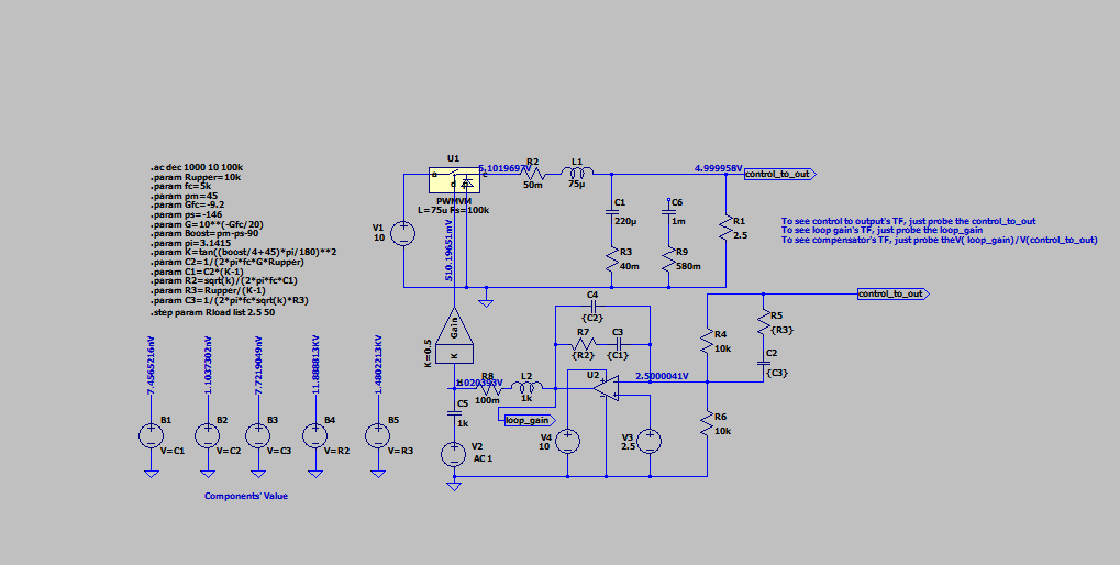
Some results: Regarding this article Stabilizing voltage mode converters with ceramic output capacitors, damping the output filter improves the phase margin. It is also useful to help us to prevent conditional stability, since the phase change is reduced by decreasing the quality factor. enter image description here
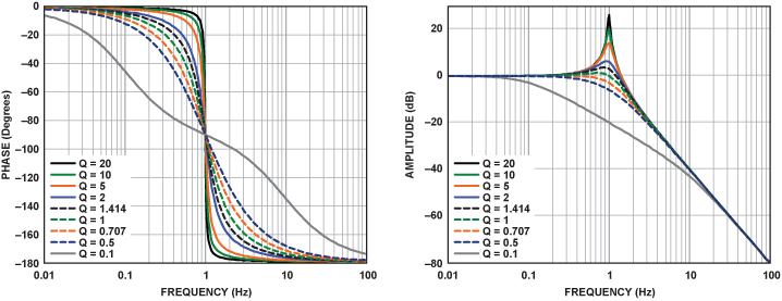
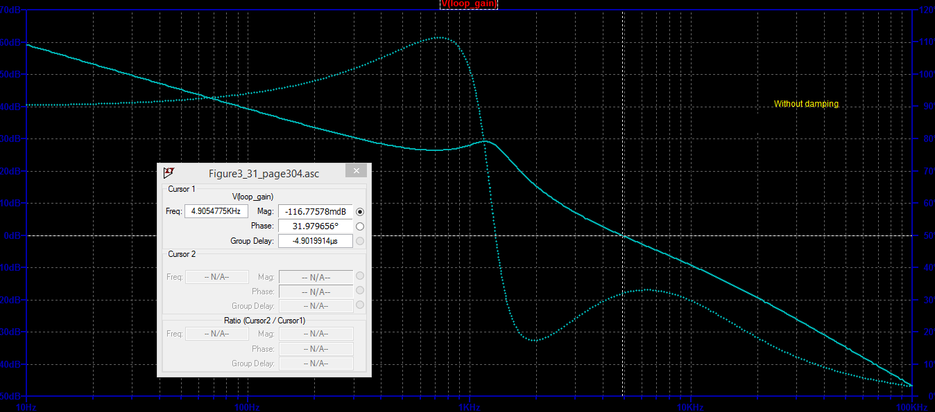
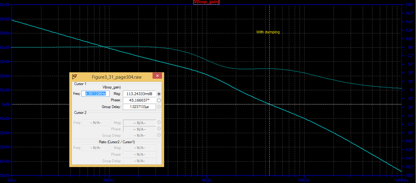
Here are also a simulation with and without damping.

enter image description here

enter image description here enter image description here

\$\endgroup\$
9
  • 1
    \$\begingroup\$ If you put a filter on the output of your buck converter, and the filter is under-dampened, then you will/can get what is known as "ringing" this is when you get large unintended transient peaks under a varying load, and is a very undesireable situation.. A properly designed switch mode psu will often have a filter on the output which reduces the ripple from switching, but if this filter is not properly designed (needs to be over-dampened) you get ringing. \$\endgroup\$
    – user173292
    Commented Jan 31, 2021 at 21:37
  • 3
    \$\begingroup\$ @Vinzent only if the converter's compensation doesn't take the filter characteristics into account properly. Just about any circuit done wrong will have problems -- that just means you should do your circuits right. \$\endgroup\$
    – TimWescott
    Commented Jan 31, 2021 at 21:57
  • 1
    \$\begingroup\$ @TimWescott "only if the converter's compensation doesn't take the filter characteristics into account properly" What do you mean by that??. If you build a switch mode psu and you put a passive filter on the output to reduce switching noise (which is very common) then unless your filter is over-dampened (or critically dampened) then I guarantie that I can make it produce large transients (in theory) with an arbitrary varying load.. \$\endgroup\$
    – user173292
    Commented Jan 31, 2021 at 22:02
  • 2
    \$\begingroup\$ @Vinzent "properly" means "correctly". If you have more than one LC section in your filter, then you're probably going to need compensation that taps each capacitor voltage, does some filtering on it, and applies it to the feedback. \$\endgroup\$
    – TimWescott
    Commented Jan 31, 2021 at 22:06
  • 1
    \$\begingroup\$ Show an example circuit of what you mean to cut through all this ambiguity. If you truly mean an extra LC filter after the buck circuit then yes, you have to be very careful about its design but I'm not going to guess without a schematic example. \$\endgroup\$
    – Andy aka
    Commented Feb 1, 2021 at 9:58

2 Answers 2

2
\$\begingroup\$

No, damping the LC filter of a buck converter should not be done.

A buck converter is an active device, and the paper you refer to is about passive power filters, and indeed when building LC filters for sensitive or noisy components like clock oscillators, the filter is damped by putting a resistor in parallel with the inductor.

\$\endgroup\$
2
  • \$\begingroup\$ Comments are not for extended discussion; this conversation has been moved to chat. \$\endgroup\$
    – Voltage Spike
    Commented Feb 1, 2021 at 12:31
  • \$\begingroup\$ It depends where the feedback node is taken and thus generally this is true. Since a buck is made up of an buck inductor and an output cap, this is where the feedback is typically taken and assuming the buck bandwidth is in excess of the natural frequency of this LC all is fine. Any additional L-C post the regulation point will require some form of damping \$\endgroup\$
    – user16222
    Commented Jun 2, 2021 at 9:11
1
\$\begingroup\$

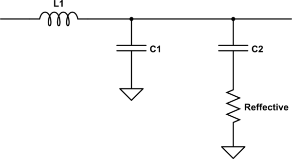
The output LC section of a buck converter is often damped, but generally not with a discrete resistor. Instead, two capacitors are used, one (usually ceramic) with a low Equivalent Series Resistance (ESR), and another one in parallel with a higher ESR (usually an aluminum electrolytic cap).

If one neglects the other parasitic impedances except the ESR of the high ESR cap, the output section of such a buck converter looks like this:

schematic

simulate this circuit – Schematic created using CircuitLab

Damping in this way is discussed in this EE Times article as well as elsewhere.

\$\endgroup\$

Your Answer

By clicking “Post Your Answer”, you agree to our terms of service and acknowledge you have read our privacy policy.

Not the answer you're looking for? Browse other questions tagged or ask your own question.