0
\$\begingroup\$

I am thinking about a relatively cheap and simple protection against USB reverse connection/reverse polarity. At the moment I am thinking about P-channel MOSFET, with the drain directed towards the USB socket. I heard that TVS diodes can also, in addition to protection against ESD, prevent reverse polarity, but I would not be able to choose them exactly. Pins D + and D- are connected via resistors to the STM microcontroller.

As it is a Type P MOSFET, the gate being low will cause the transistor to conduct from the drain to the source. I predict that when the USB plug is plugged inversely, the MOSFET gate will be high and the MOSFET will shut off, preventing damage to the receiving circuit.

But these are only my modest theoretical considerations, and I would like to ask if I have not made a logical error here or if something is not ok from a practical point of view.

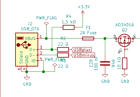
enter image description here

\$\endgroup\$
2
  • \$\begingroup\$ This will work fine. In practice reverse polarity protection is provided by the connector itself (i.e. you can't plug it in wrong). If you're only using your device with commercial products (i.e. not hobbyist parts) then I wouldn't worry about reverse polarity protection. Have never seen it in the wild, even with the cheap cables. \$\endgroup\$
    – Jon
    Feb 1, 2021 at 23:12
  • \$\begingroup\$ Agree - Unless somebody makes their own USB cable, you can be very sure the VCC will be VCC and GND is GND. 2A fuse is possibly also somewhat redundant as USB ports are internally current limited to about that value (or alot less). \$\endgroup\$
    – Kyle B
    Feb 2, 2021 at 1:07

1 Answer 1

2
\$\begingroup\$

It looks like the FET protects from inverse polarity, but it is not needed as it is not possible to have wrong polarity out of an USB cable.

I would also like to point out that tying the D+ pin via resistor directly to 3.3V will not allow the MCU to control when it is ready to enumerate, so depending on what the MCU program does, it may fail to enumerate if it is not immediately ready with the USB peripheral at boot.

Another thing is, by grounding the ID pin, you are signaling that this device is an OTG master, not a USB device, so that won't work.

Also the connector shield is directly connected to ground, that may not be what you want either.

\$\endgroup\$
4
  • \$\begingroup\$ Believe or not, but I had an experience with factory confused wires inside the usb cable :) I am trying to read a bit about ID and shield connection, but I do not understand the D + connection issue yet. Is it voltage value of 3.3V or just D + should be left without this connection? \$\endgroup\$
    – Karlsson
    Feb 2, 2021 at 13:57
  • \$\begingroup\$ The problem is permanent connection to 3.3V. Even if MCU is in reset or booting or otherwise not ready yet for enumeration, the resistor signals to PC that device is ready for enumeration. PC may determine that the enumeration fails and stop communicating with the device. There is also chance that the pull-up resistor is internal to the MCU so it may not be necessary. \$\endgroup\$
    – Justme
    Feb 2, 2021 at 14:57
  • \$\begingroup\$ Hmm, I use STM32F103C8 (datasheet says "To be compliant with the USB 2.0 full-speed electrical specification, the USBDP (D+) pin should be pulled up with a 1.5 kΩ resistor to a 3.0-to-3.6 V voltage range"). I think you mean this variant with control through a bipolar transistor controlled by a microcontroller at the end of the base. To be honest, I did not see, for example, in Bluepill there was such a solution (there was also only a permanently connected resistor). If the pull-up control in such a way is the best way, would you recommend me where to read about how to program it correctly? \$\endgroup\$
    – Karlsson
    Feb 3, 2021 at 22:38
  • \$\begingroup\$ On STM32F103 (and maybe STM32F303 too), if you have a permanent pull-up on D+, the way to simulate a disconnect is to switch PA12 to the output mode and output 0; to connect USB again, switch PA12 to the input mode. Your USB stack may offer a way to supply your own functions or macros for that purpose — e.g., for ChibiOS you can replace usb_lld_connect_bus() and usb_lld_disconnect_bus() in board.h. \$\endgroup\$ Jul 15, 2022 at 22:08

Your Answer

By clicking “Post Your Answer”, you agree to our terms of service and acknowledge that you have read and understand our privacy policy and code of conduct.

Not the answer you're looking for? Browse other questions tagged or ask your own question.