0
\$\begingroup\$

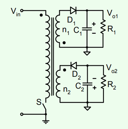
Where does the additional energy for flyback with multiple outputs come from?

It appears that I can add as many secondary outputs as I want, but the primary voltage is Vin, and the primary current can be deduced from V=Ldi/dt => i(t) = Vin*t/L (when switch is on), therefore power in primary is constant (V*I), therefore I am not sure where the power for the additional secondary windings come from if the power in the primary stays the same. Thought that maybe it has to do something with voltage\current mirroring to the primary.

enter image description here

\$\endgroup\$

2 Answers 2

5
\$\begingroup\$

where does the additional energy for flyback with multiple outputs come from?

The primary voltage is "held across" the primary inductance for as long as it takes to acquire sufficient energy to match the energy requirement of the secondary load(s). This is where the control of duty cycle comes in. A higher power requirement in the load(s) means that the energy transferred in each switching cycle must increase and that means increasing duty cycle in DCM or raising the average primary current in CCM.

$$\text{Total load power = energy transferred each cycle}\times \text{switching frequency}$$

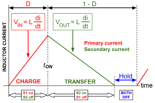
In DCM (see picture below) you only get more energy per cycle by increasing the duty cycle.

Primary and secondary current waveforms in DCM. Transformer ratio is 1:1: -
enter image description here

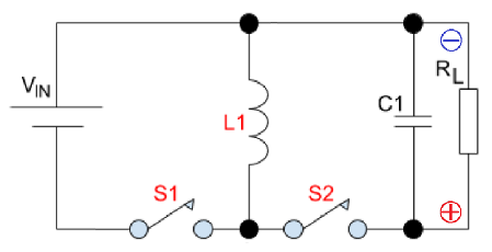
Equivalent circuit: -

enter image description here

As load power increases, the duty cycle increases giving more time for the primary to "charge" with energy. The "hold" time will shorten as the secondary power requirement grows. But remember, the basic flyback circuit cannot do this on its own; it needs a controller that monitors one of the output voltages (the "chosen one") and adjusts duty cycle to keep that voltage regulated.

The other windings on the secondary side are a little bit outside the control loop and may grow their voltages a few percent as the controller increases the duty cycle to maintain the "chosen" secondary voltage regulated.

Pictures from here and here.

therefore power in primary is constant

No, it's dependent on duty cycle i.e. how long you apply Vin to the primary winding for.


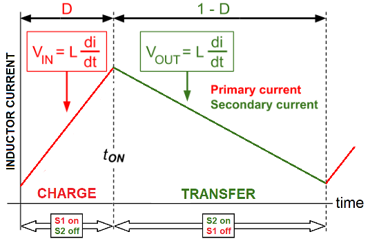
Edited to add CCM waveforms: -
enter image description here

In CCM, if the load current becomes too high, the output voltage will tend to droop (and di/dt will flatten). The knock-on effect of this is that there will be more magnetic field in the core when the charging period restarts and, at the end of the charging period, the peak primary current will naturally be a little higher. Thus, duty cycle remains the same but, the average primary current has increased to deliver the increased secondary energy.

\$\endgroup\$
12
  • \$\begingroup\$ But flyback transfer function is Vo/Vi = n*D/(1-D) (where D is the duty cycle, and n is the windings ratio), so if we keep Vo and Vi constant, we can derive the duty cycle. But you say that different loads change the Duty cycle, but the whole point is keeping constant Vo, Vi (and therefore constant Duty cycle), so how is it logical? \$\endgroup\$
    – Jonathan
    Commented Feb 2, 2021 at 11:55
  • \$\begingroup\$ @Jonathan Higher output current from the transformer (note: not the PSU output current) affects the slope of the green line. If you draw more current in total, the line goes to 0 faster. \$\endgroup\$ Commented Feb 2, 2021 at 11:58
  • 1
    \$\begingroup\$ @user253751 that's not really true except when dealing with load changes i.e. transients. Once the load has stabilized, the slope of the green line is related to the output voltage and the equivalent secondary inductance. \$\endgroup\$
    – Andy aka
    Commented Feb 2, 2021 at 12:29
  • 1
    \$\begingroup\$ @Andyaka The same principles apply. In DCM, the energy transfered in one cycle depends upon duty. But in CCM, the energy transfered in one cycle depends not only on duty, but on the residual current through the inductor from the previous cycles. \$\endgroup\$ Commented Feb 2, 2021 at 14:21
  • 1
    \$\begingroup\$ @MathKeepsMeBusy OK, you've convinced me - I shall make an amendment. \$\endgroup\$
    – Andy aka
    Commented Feb 2, 2021 at 14:22
0
\$\begingroup\$

Essentially the flyback principle is to inject to C1 and C2 charge boosts often enough to keep the voltages at he wanted values. The charging pulses are also designed to be small enough to prevent too high voltage jumps.

You at first charge some magnetic energy to the core of the transformer by letting S conduct a while. The primary current grows with rate Vin/primary inductance. It's amperes/second if Vin is in volts ant the inductance is in henries.

Then you let the magnetic field collapse by opening S. Magnetic field has the property it never collapses instantly. It generates just as much electric field as needed to cause enough voltage to the windings to let the current flow in at least one of the windings so that the current decays gradually, not instantly. The induced pulse hopefully goes through the diodes to charge C1 and C2 and S is strong enough to hold the induced voltage with no smoke.

The idea is to generate induced pulses often enough to keep C1 and C2 in the wanted voltages. The control circuit takes care of this aspect. If there's not enough new current pulses to C1 and C2 the voltages drop.

If it happens that you feel you do not know well enough how the inductors work check this old case: https://electronics.stackexchange.com/questions/282053/how-does-the-inductor-really-induce-voltage?r=SearchResults&s=1|63.9320

\$\endgroup\$

Your Answer

By clicking “Post Your Answer”, you agree to our terms of service and acknowledge you have read our privacy policy.

Not the answer you're looking for? Browse other questions tagged or ask your own question.