On some PCB designs, specific traces are routed in curious ways. This probably has to do with high frequency design considerations and general signal behavior that I am not familiar with.
Let's take this PCB (somewhere from the web) as an example. It shows part of a PCIe card with SATA routing and DDR2 RAM:
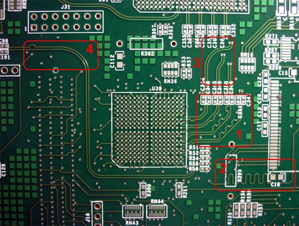
I highlighted 4 areas that qualify as unusual trace layout (from my perspective).
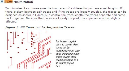
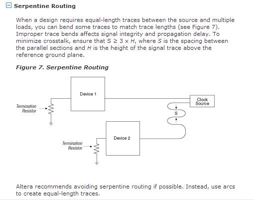
- What are those shapes supposed to achieve? How do designers come up with what pattern is required?
- Another example of wave shaped, antenna like routing.
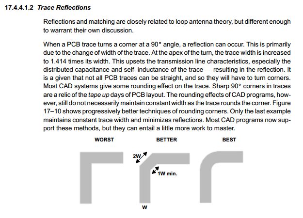
- This is fairly rare. But obviously the designer deliberately avoided 45° traces. Why?
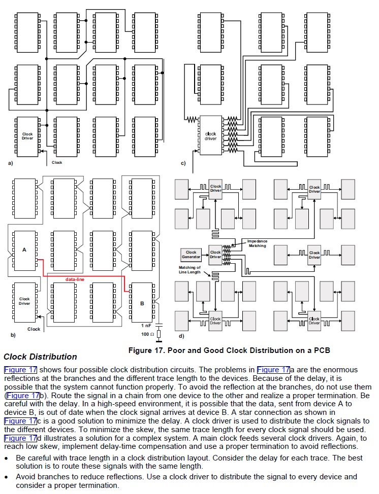
- Curves again and a single "pulse" within the trace. How can this have any significant effect?
So what are the use cases and benefits of this techniques?
I want to be able to take those into consideration when doing future PCB designs.

