0
\$\begingroup\$

I am trying to design a simple square wave inverter (15V input from my power supply). For this purpose I will design a H-bridge with 4 MOSFETs controlled by the Arduino (5V or 3.3V output). The thing is, how can I make my power supply and Arduino work together? I only need the Arduino to control transistors (to make them let current pass).

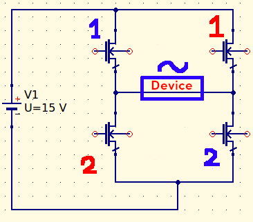
MY CIRCUIT

Sorry for the bed design, as it is my first year in Electrical Engineering. This is the incomplete circuit design. The transistors in the scheme will be controlled by the Arduino. It will make blue ones OPEN first, then it will make red ones OPEN. So polarity will constantly change for the "Device." But I don't know how I can integrate the 5V Arduino here.

\$\endgroup\$
2
  • \$\begingroup\$ are you asking how to connect an Arduino to a 15 V power supply? ? \$\endgroup\$
    – jsotola
    Commented Feb 20, 2021 at 19:29
  • \$\begingroup\$ No, I will power it from my PC. But I will also have to use a 15 V supply. Arduino is only there to control transistors and powering it with 15 V would burn it (?) \$\endgroup\$ Commented Feb 20, 2021 at 19:30

2 Answers 2

2
\$\begingroup\$

You connect the Arduino ground to the ground of your power supply and H-bridge driver. Make sure that the high currents have a direct ground path from the H-bridge back to the power supply and not through the Arduino's ground.

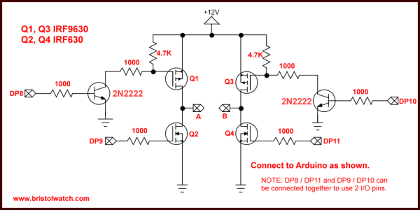
enter image description here

Figure 1. A simple driver circuit for H-bridge. Image source: Bristol Watch.

  • Since the Arduino can only switch up to 5 V it cannot "reach high enough" to control Q1 and Q3. For this reason the 4.7k pull-up resistors are added and the 2N2222 transistors (or any small NPN) are added to turn on Q1 and Q3.
  • Note that Q1 and Q3 are PMOS; Q2 and Q4 are NMOS. Your design shows four NMOS. You can do that but the switching circuit will be more complex.
  • Connect Arduino ground to H-bridge ground.
\$\endgroup\$
7
  • \$\begingroup\$ Can you please give me a visual illustration? Sorry, I am very new to electronics and my native language is not English either. \$\endgroup\$ Commented Feb 20, 2021 at 19:31
  • \$\begingroup\$ If you edit your question to show your H-bridge design I can edit my answer. Your English is good. \$\endgroup\$
    – Transistor
    Commented Feb 20, 2021 at 19:35
  • \$\begingroup\$ Okay, lemme try \$\endgroup\$ Commented Feb 20, 2021 at 19:43
  • \$\begingroup\$ Done @Transistor \$\endgroup\$ Commented Feb 20, 2021 at 20:01
  • \$\begingroup\$ @İbrahimİpek See the update. \$\endgroup\$
    – Transistor
    Commented Feb 20, 2021 at 20:46
1
\$\begingroup\$

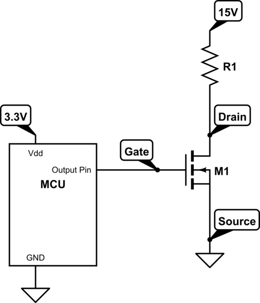
Different machines/circuits can connect their SIGNALS together while having different power cables with different voltages running to them. What matters in this case is that the signal ports connecting to each other can handle each other.

More applicable for your H-bridge is below. Inside the MOSFET transistor is a barrier between the gate and the rest of the MOSFET. That barrier blocks the 15V from getting to the 3.3V (within reason). It allows a smaller signal applied between the gate and source terminals to control a larger signal across the drain and source terminals.

The base terminal of a BJT (another common type of transistor) is similar.

schematic

simulate this circuit – Schematic created using CircuitLab

\$\endgroup\$
6
  • \$\begingroup\$ Thanks, this makes sense. So just plugging my Arduino to my PC and the output pin to gate will be enough? \$\endgroup\$ Commented Feb 20, 2021 at 20:04
  • \$\begingroup\$ The MOSFET is not controlled by the voltage at the gate. This is impossible because voltage is measured between two points. The MOSFET is controlled by the voltage BETWEEN the gate and source terminals. So in the example above, your Arduino pin needs to connect to the gate and the GND. However, you will quickly notice that in an H-bridge not all MOSFETs have their source terminals connected to the GND of the Arduino. This is an issue that you will need to deal with known as "high-side gate drive" which is another topic for another question once you look into it more. \$\endgroup\$
    – DKNguyen
    Commented Feb 20, 2021 at 20:07
  • \$\begingroup\$ The MOSFET only cares about and can only "see" the voltage between its terminals. If the MOSFET's source terminal is not connected to GND, and you apply a gate voltage that is referenced to GND, the MOSFET cannot know what that voltage is because it cannot see GND. It only knows what voltage is appearing across gate-source. \$\endgroup\$
    – DKNguyen
    Commented Feb 20, 2021 at 20:07
  • \$\begingroup\$ In that case upper two MOSFETs will fail to work. Hmm... Can I solve it by simply using a BJT (although it is not good for frequency)? Or should I go for what you call "High-Side Gate Drive"? \$\endgroup\$ Commented Feb 20, 2021 at 20:33
  • \$\begingroup\$ I uploaded a photo above if you have not seen it, I am talking in terms of it \$\endgroup\$ Commented Feb 20, 2021 at 20:35

Your Answer

By clicking “Post Your Answer”, you agree to our terms of service and acknowledge you have read our privacy policy.

Not the answer you're looking for? Browse other questions tagged or ask your own question.