12
\$\begingroup\$

I'm a total beginner with circuitry, but for thinking through a project for I want to build as a hobby some day, I'd need an "inverted relay."

A relay is, from my understanding this:

I have a main powerline that I either want on or off, and I want to control whether this is on or off by sending little bit of power through another powerline (i.e a control wire, e.g. controlled from a yes-no-switch). It's on when there is electricity in the control wire and off when not.

Now, I'd need something that breaks the current in the main line if it's set.

I can imagine that this very well exists, but through my lack of knowledge in this field I'm missing the correct terminology to google this properly.

So what's this name if such a component exists?

\$\endgroup\$
9
  • 15
    \$\begingroup\$ You're overthinking a relay. A relay is simply a switch that is operated by a magnet. That magnet is generally powered from a low voltage like 5 V DC or 24 V DC. When power is applied to the magnet, the switch changes state. That can be on => off or off => on depending on the relay. Most relays have this combined into one, a 3 contact switch where one side opens while the other side closes. You might want to read: circuitstoday.com/working-of-relays \$\endgroup\$ Commented Feb 21, 2021 at 12:48
  • 3
    \$\begingroup\$ A picture is worth a thousand words: (1) Relay Switch Types - SPST (Single Pole Single Throw) NO/NC (Normal Open / Normal Close), DPST(Double Pole Double Throw) NO/NC - Electronics Tutorials electronics-tutorials.ws/io/io_5.html. Cheers. \$\endgroup\$
    – tlfong01
    Commented Feb 21, 2021 at 13:25
  • 4
    \$\begingroup\$ NC (Normally Closed) vs NO (Normally Open) contacts. Note that a CO (Changeover) relay gives both options; just connect to the pins you need. \$\endgroup\$
    – user16324
    Commented Feb 21, 2021 at 13:32
  • 2
    \$\begingroup\$ As others have explained, what you want is a ... relay! But!! Relays are rated according to how much voltage/amperage they switch - for your application and for your safety (don't burn down your house!) make sure you get one rated to switch line voltage at the power level you need. (And, it should go without saying: Make sure you know what you're doing before starting to play around with line voltage!) If it was me I'd go with something someone else already built and got UL approved, maybe something from here \$\endgroup\$
    – davidbak
    Commented Feb 21, 2021 at 21:39
  • 3
    \$\begingroup\$ @Circuifantasist's answer contains some useful points. While the use of NC or NO contacts, as mentioned by others, will often do what you want. - 1. Changing the coil connection from ground to V+ is an obvious but easily overlooked method of "reversing" operation. 2. Using permanent magnet biasing so that the coil counteracts the pm field is also "obvious" but verges on magic in some applications. A relay is normally operated with NO voltage applies and releases when power is applied. Very seldom seen. Can be a life saver. \$\endgroup\$
    – Russell McMahon
    Commented Feb 22, 2021 at 13:03

5 Answers 5

37
\$\begingroup\$

schematic

simulate this circuit – Schematic created using CircuitLab

Figure 1. A typical relay circuit.

How it works:

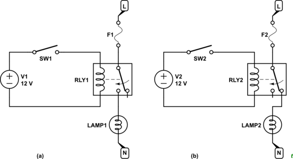
  • A control signal, 12 V in Figure 1a, and a small switch is used to power the relay coil.
  • The relay coil pulls the contact across from the NC (normally closed) contact to the NO (normally open) contact. Mains power can then flow to the lamp.

Alternatively the lamp could be fed from the NC contact as shown in Figure 1b. In this configuration SW1 turning on will turn off the lamp.

When specifying the relay you choose the coil voltage, the contact rating (both voltage rating, current rating and DC or AC) and the contact type - a changeover contact is shown in Figure 1.

\$\endgroup\$
23
\$\begingroup\$

Yes. How a relay respond to input current is defined by the words "Normally Open" and "Normally Closed".

The word "normal" refers to the relay not being activated.

The word "open" means the circuit is broken and the word "close" means the circuit can conduct current.

So a normally open relay is "off" until it is activated (like what you described in your question) and a normally closed relay is "on" until it is activated.

You are looking for a "normally closed" relay usually indicated as NC or N/C.

\$\endgroup\$
1
16
\$\begingroup\$

Yes, relays come with many configurations, and you can select a relay that has a normally connected connection instead of normally open connection. A double throw relay has both connections available.

\$\endgroup\$
7
\$\begingroup\$

Short answer: A relay can be "inverted" by "inverting" either the coil (connecting it to Vcc) or contacts (making them normal closed instead normal open).

Structure. A relay can be considered as consisting of two cascaded parts (stages) - an input part (coil) and an output part (contacts). They can be thought of as a kind of "converters" with input and output: the coil converts the input voltage into a magnetic field and armature movement; the contacts convert the armature movement into a resistance (on/off circuit). Each of them can be "noninverting" and "inverting" so that a total of four combinations are possible. To make an "inverted" relay, only one of "converters" should be inverting.

Coil "inverting". We can assume the relay coil is "noninverting" if its other (neutral) end is connected to ground... and the coil is "inverting" if it is connected to the positive rail:

  • In the first case (grounded coil), there is a voltage across it and power is dissipated when the input voltage is high. The input current enters the coil; so the driving stage must be able to source a current. When the input voltage is low, there is no voltage across and current through the coil; so power is not dissipated.

  • In the second case (connected to Vcc coil), there is no voltage across it when the input voltage is high since the two voltages are subtracted (mutually neutralized) and the resulting voltage across the coil is zero; this is a kind of a voltage biasing. As a result, there is no current flowing and there is no power dissipated. When the input voltage is low, there is a voltage across the coil and power is dissipated. The input current exits the coil and enters the driving stage; so it must be able to sink a current.

Contact "inverting". We can consider the relay contact noninverting (normal open) if it is on when there is a voltage across (current through) the coil... and inverting if it is off when there is a voltage across (current through) the coil.

  • An extravagant way to invert the relay operation is to connect its contacts in parallel instead of, as usual, in series to the load. However, in this case, the load should be powered by a current source.

Field inverting. An even more extravagant idea is to "invert" the magnetic field of a reed relay by an additional magnet with an opposite polarity (magnetic biasing)...

Note: I have used in my explanations above some non-standard (descriptive) names for the purposes of understanding. If necessary, I can give additional explanations.

\$\endgroup\$
2
  • 3
    \$\begingroup\$ +1 See my comment on the OP's question :-) \$\endgroup\$
    – Russell McMahon
    Commented Feb 22, 2021 at 13:03
  • 2
    \$\begingroup\$ @Russell McMahon♦, Thank you for your attention; it costs little but means a lot. As you can see, my goal is to make young people learn to think and understand, not just to know. That is why I focus on curious and little-known properties of elements and circuits... and not on well-known banal facts around them... I want to make them inventors, not just neat performers. Another interesting feature of relays is their hysteresis which can make them act as latches with "internal positive feedback"... and, of course, connecting the contacts back to the coil ("external positive feedback")... \$\endgroup\$ Commented Feb 22, 2021 at 14:06
5
\$\begingroup\$

Other answers are correct regarding the operation of a relay, but I'll try to address the potentiel XY problem.

When switching a main power line, there is a lot of safety issues that need to be taken into consideration and the best approach depends on the load you're trying to switch.

Switching an electrical appliance or an outlet

For switching a standard appliance (<15 Amp) you could use a relay (with the correct ratings), an overcurrent protection (e.g. a fuse to protect the relay), a control circuit (to drive the relay), a power supply (for the control circuit) and a way to isolate the control signal from the main voltage (either a wireless controller or an isolation circuit based on optocouplers if you want a control wire). All of that needs to be fitted inside a double insulated enclosure to ensure the safety of users.

Instead of building that yourself, you could simply use a $20 smart plug and focus on the logic part of your project (those plugs usually uses the ZigBee protocol or even Wifi so you can easily drive then from a microcontroller/arduino/raspberry pi).

Switching a whole circuit

If you need to switch an entire circuit, you can use the same approach as for a single outlet with a major caveat : you are not building an electrical appliance anymore, you are modifying the electrical installation of the building. Since your device (relay+control circuit) would now be part of the electrical installation, it would need to be certified to conform to your local electrical code.

This most definitely eliminate any possibility of a DIY solution if you want to conform to code. In any case, you should use an out-of-the-box relay module designed and certified to be put in a distribution board.

Switching the main power supply

Since the main supply is also part of the electrical installation, the same regulation considerations apply here as well.

But switching the main power supply of an entire installation involve working with a lot more current (at least 60A but usually 100A-200A for a 110/120V installation). Working with that amount of current implies a lot of new things to worry about, including arc suppression. Your device would need a way to safely contains and extinguish those arcs in order not to stay stuck in a close position, burn-out or fail prematurely.

There are out-of-the-box relay modules able to handle large amount of current but their price increase exponentially with the amount of current they are rated for. I you don't really need the responsiveness of a relay (usually <10ms), there are other electro-mechanical solutions more suited for switching that amount of current. They usually consists of a motorisation on top of a mechanical circuit breaker which is slow (between 500ms and a few seconds) but a lot easier to implement than a relay.

\$\endgroup\$
1
  • 4
    \$\begingroup\$ Over 15 amps it becomes a contactor. This is line voltage we're talking about here +1, which ironically this is the wrong site to ask about doing things yourself. \$\endgroup\$
    – Mazura
    Commented Feb 22, 2021 at 18:58

Your Answer

By clicking “Post Your Answer”, you agree to our terms of service and acknowledge you have read our privacy policy.

Not the answer you're looking for? Browse other questions tagged or ask your own question.