1
\$\begingroup\$

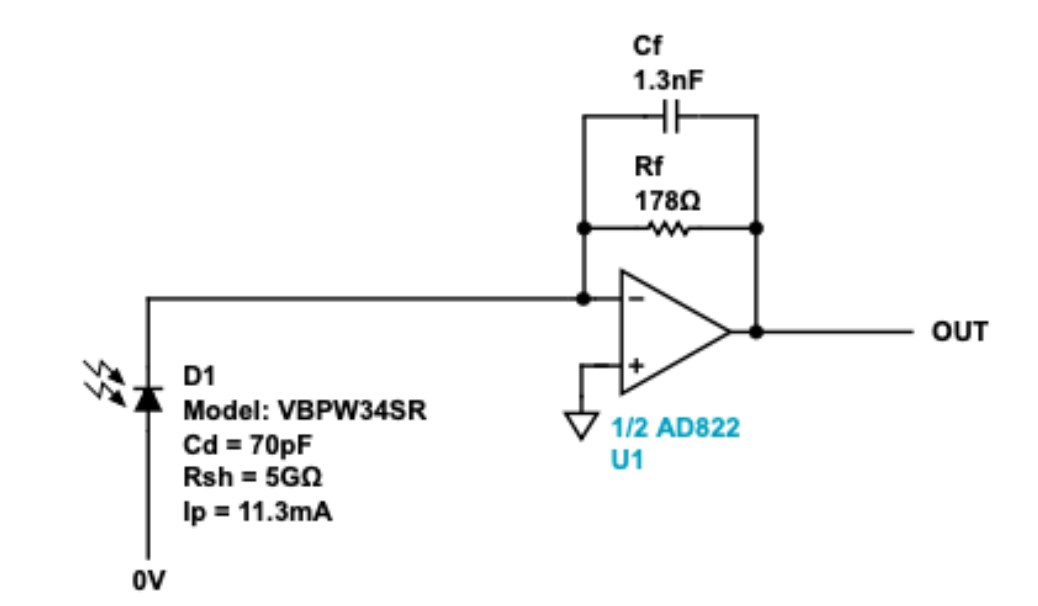
I am trying to measure the voltage coming out of my op-amp after connecting it to my photodiode. As a photodiode, I am using a BPW34S from Vishay, and the op-amp is an AD822ANZ from Analog Devices. According to the Analog Devices Photodiode Circuit Wizard, the following image should be my connection:

enter image description here

The cathode of my photodiode is connected to the op-amp, while the anode is connected to the ground. I am using a 9 V battery to power my op-amp as a single supply. The '-IN1' is connected as shown in the above image, '+IN1' is connected to the ground, as is 'V-', and 'V+' is connected to the positive side of the 9 V battery. As a ground, I am using the negative side of the battery. I have also tried using the 5 V and GND output of a Raspberry Pi 4, but I thought that maybe I was not getting enough voltage.

I have measured the voltage between Vout and Ground of the battery with a voltmeter, but I always get 0 V as output from my op-amp, and there is no change when I put more light on my photodiode.

My photodiode works when I connect it to a resistor and measure the voltage passing through the resistor, but I need it to work with an op-amp as I want to connect it to an ADC afterwards.

Am I doing something wrong with the wiring, or is there a problem with my op-amp?

\$\endgroup\$
4
  • 2
    \$\begingroup\$ Double check anode and cathode as otherwise, this circuit should work and the op-amp is a good choice. \$\endgroup\$
    – Andy aka
    Commented Mar 2, 2021 at 15:02
  • 1
    \$\begingroup\$ Your circuit looks like a TIA (Trans Impedance Amplifier) to me which converts the current from the photodiode into a voltage. As the current from the photodiode is usually quite small, the TIA needs a large conductance. In your circuit that conductance is very small because Rf is only 178 ohms, if your photodiode really outputs 11.3 mA then that could be OK though. If you want to amplify the voltage of the photodiode, this is not the correct circuit. You might want to build a "buffer" circuit using the opamp. \$\endgroup\$ Commented Mar 2, 2021 at 15:12
  • 1
    \$\begingroup\$ You will need more than 10mW of light to create 11mA of photocurrent. That is a lot. How much light are you putting on it? \$\endgroup\$ Commented Mar 2, 2021 at 15:26
  • \$\begingroup\$ Yes that was the problem of my circuit. I optimized it to realise when a laser was shining into it (hence the small resistance) but was testing it with normal light and the light from my phone. When changing the resistance to around 100kOhm, the measured voltage is definitely higher and reacts more! Thanks a lot! \$\endgroup\$
    – Samboff
    Commented Mar 2, 2021 at 15:32

1 Answer 1

2
\$\begingroup\$

If you are using a single supply, ground isn't in your allowable common mode input range, which would stop at 100 mV for the AD822. You need a negative supply, or a different circuit.

Also, current would drive this circuit output below zero, which won't work with a single supply.

A quick fix would be to tie the anode and noninverting input positive with the same positive voltage reference

\$\endgroup\$
4
  • \$\begingroup\$ If I move both to the positive 9V side of the battery, I just get a reading of 8.6 V, which doesn't change with the amount of light intensity. This is also the V when I read the Voltage of the battery. \$\endgroup\$
    – Samboff
    Commented Mar 4, 2021 at 8:22
  • \$\begingroup\$ 9V is bad on the other side. Op amps don't work too near the rails \$\endgroup\$ Commented Mar 4, 2021 at 13:08
  • \$\begingroup\$ You need a voltage in between \$\endgroup\$ Commented Mar 4, 2021 at 13:08
  • \$\begingroup\$ The AD822 has a voltage range to -0.2 V below Vs. Did you read the data sheet? \$\endgroup\$
    – user319836
    Commented May 7, 2023 at 3:30

Your Answer

By clicking “Post Your Answer”, you agree to our terms of service and acknowledge you have read our privacy policy.

Not the answer you're looking for? Browse other questions tagged or ask your own question.