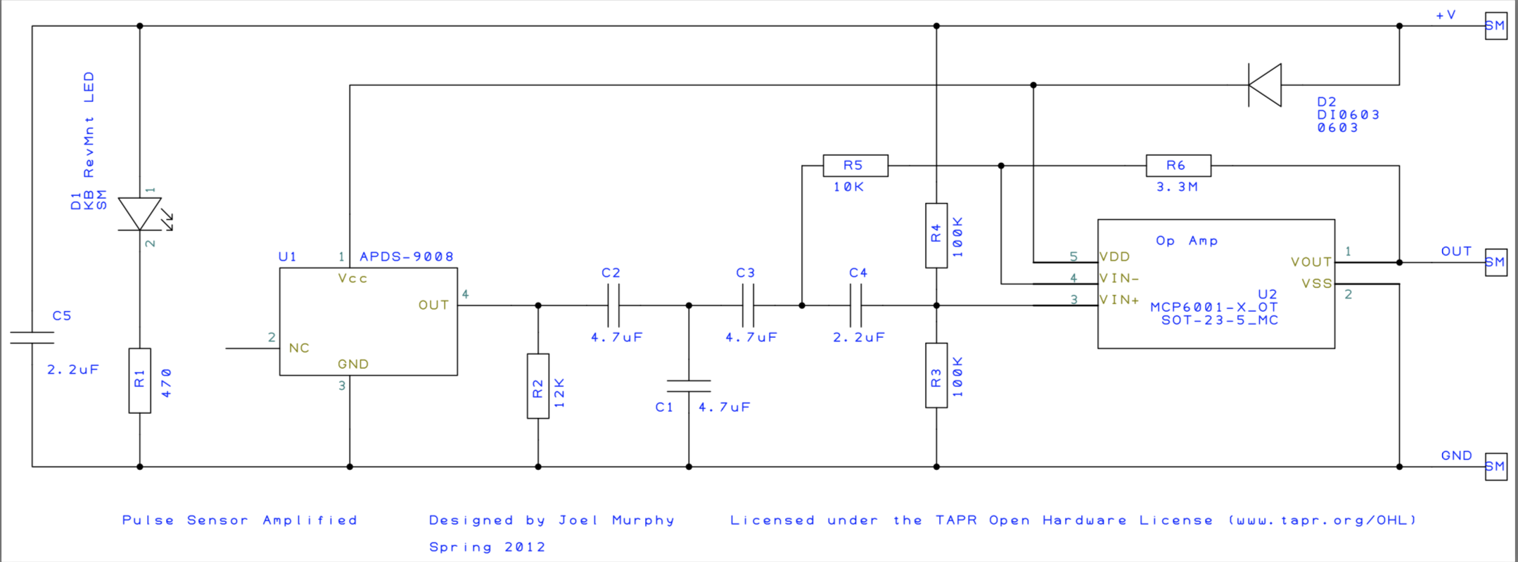
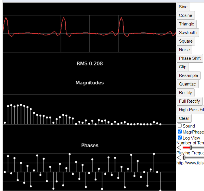
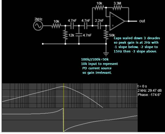
I am studying RC filtering in order to try and understand this circuit which was previously discussed in(What kind of filtering does this op-amp perform?).
The answers gave advice on testing the response to a sine wave sweep which should show it's filtering of undesired noise/interference such as mains electricity at 50/60Hz. I want to follow the path/modifications to the signal itself which to my knowledge is a direct current produced by the photodiode. Can this current pass through the capacitors and if so how?
I am trying to identify sub-components of the circuit and learn what effects they are having, please correct any misunderstanding:
1.The two 100K resistors are there to introduce an offset voltage so as to center the Op-Amp output at 2.5V? They do not have any additional effects?
2.The feedback path from Vout through two series resistors R6 (feedback resistor)& R5 forms another voltage divider. The fact that R6 is far far larger means only a very small voltage difference will be seen at VIn-.
3.Lastly, the feedback branch R5 and C4 appears to me to be a differentiator but I am unsure how to test this in simulation as I am interested in how the circuit processes the signal of interest - a varying direct current, rather than the AC noise of a sweep signal.
Any advice or input appreciated.


