0
\$\begingroup\$

A brief summary: I work at a small workshop/factory, and we've got a single three-phase compressor for the whole factory, a week ago the compressor controller flat-out died and that left the entire place without air, which is critical for production.

The compressor has to keep air pressure at a set interval (6 - 8) Bar If it goes to low the machines stop, and if it goes to high the tank safety valve activates and all air goes out. The compressor is relatively simple at an electrical level, just a three-phase motor, a valve to let the compressed air into the tank, and 3 contactors to do a star-delta startup.

Some usefull info: Importing replacement parts/servicing the compressor is a no-go, it is chinesse in origin, with no representative here in my country, and our trade laws make importing a new controller more expensive than just buying a new compressor, (Wich is something we are really trying to avoid as doing so would be seriously expensive, and the mechanical part of the compressor works, it's just the pressure control that's busted)

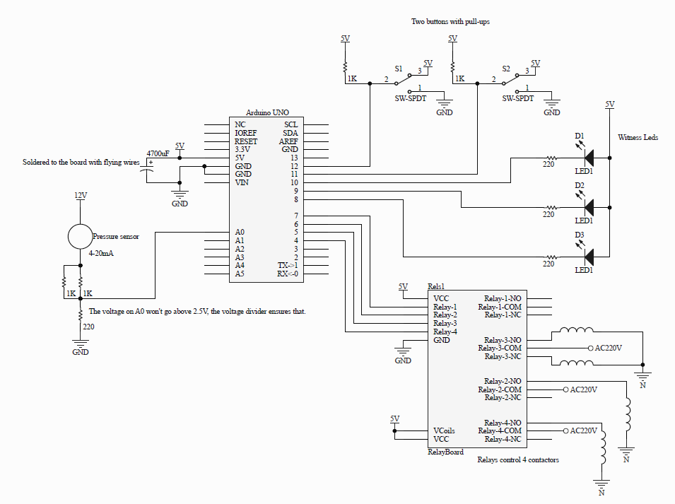
So to solve this problem I grabbed an arduino UNO and a relay pcb and coded a simple program which manages the star-delta operation, and controls the air pressure valve.

The pressure sensor requires at least 10V to work properly and for that reason there's a 12V switching power supply coneccted to it.

The project works, but it resets randomly, there's no pattern one day it might reset every 15 minutes and another every 3 hours, the conecctions between the arduino and everything else are all done using cables with pins, and the whole thing shakes a fair bit becouse it's mounted on the compressor.

Things i've tryed so far: -Removed both the reset button and the capacitor that allows the Ch340 to reset the arduino. -Soldered a 4700uF capacitor directly to the arduino board, thinking that maybe the connectors where shaking loose and the arduino getting powered down for just a second. -Added an external 5V 5A switching power supply to the arduino, and powered it directly through the 5V pin (not the usb B port)

Finally my question is, does anyone know of any other reason why the arduino could be resetting itself? The only other thing i can think of is something on the ac lines.

I'll show the code if need be, but I'm not using pointers, or dinamic memory or anything that could cause a software reset.

Simple connection diagram

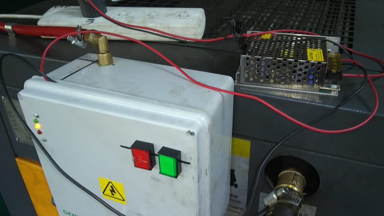
Photo of the arduino mounting

I can't show you a photo of the inside of the box becouse we can't stop the compressor, sorry i forgot.

\$\endgroup\$

1 Answer 1

2
\$\begingroup\$

Welcome to the wonderful world of EMI, and why real industrial-hardened PLCs cost much more than the limited processing power might suggest.

  1. Add series resistors on each digital output line and on the analog input line. Maybe 4.7K on each (except the LEDs, keep them within the box if possible, and the relay drive lines, which are probably opto-isolated).

  2. Connect the power supply negative to earth at one point.

  3. The shield on the sensor line should be connected to the housing at the point of entry. And there should be a shield.

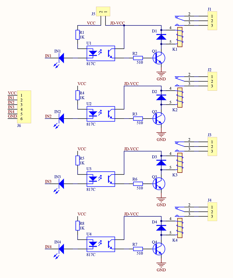
  4. Assuming your relay board is opto-isolated (as in the below schematic), use a separate supply for the 5V relay coils, not the Arduino. Do not connect them together, either ground or 5V. Keep the wires well separate. This and the sensor lines are my guess for the main culprits.

  5. Keep all the low voltage wires separate from the mains switched wires, at least 150mm where possible.

enter image description here

\$\endgroup\$
4
  • \$\begingroup\$ I'm having trouble understanding points 2 & 4, when you say connect the power supply negative to earth you mean connect all GND outs from the dc supplies or all the Neuter inputs from said supplies? also this: "either ground or 5V" does this mean i should keep both 5V and GND from the coils from a different supply or is sharing one rail (GND preferably) okay? because my relay board is exactly like your schematic, which means that GND is already shared whether i like it or not. \$\endgroup\$ Commented Mar 5, 2021 at 3:21
  • \$\begingroup\$ Also a couple of clarifications: that huge red tube connecting to the box is an air tube, the sensor lines are unshielded, but are no longer than 100mm, and while the sensor does have an earth pin for it's metallic housing, it's not connected. Another note I read somewhere that it's a good Idea to do a Star-Ground connection scheme, do you think this would change anything? Also the box is plastic, would putting everything inside a metal one and connecting it to earth make everything better or worse? \$\endgroup\$ Commented Mar 5, 2021 at 3:21
  • \$\begingroup\$ GND is not shared. GND on the PCB is only for the relay coils. There is no GND on the Arduino side, nor does there need to be. \$\endgroup\$ Commented Mar 5, 2021 at 3:23
  • \$\begingroup\$ Finally got around to trying this answer last saturday and after 3 days of operation the compressor has reset itself only once (which is as good as it'll probably get), thanks for help, I'll be accepting the answer. \$\endgroup\$ Commented Mar 8, 2021 at 19:07

Your Answer

By clicking “Post Your Answer”, you agree to our terms of service and acknowledge you have read our privacy policy.

Not the answer you're looking for? Browse other questions tagged or ask your own question.