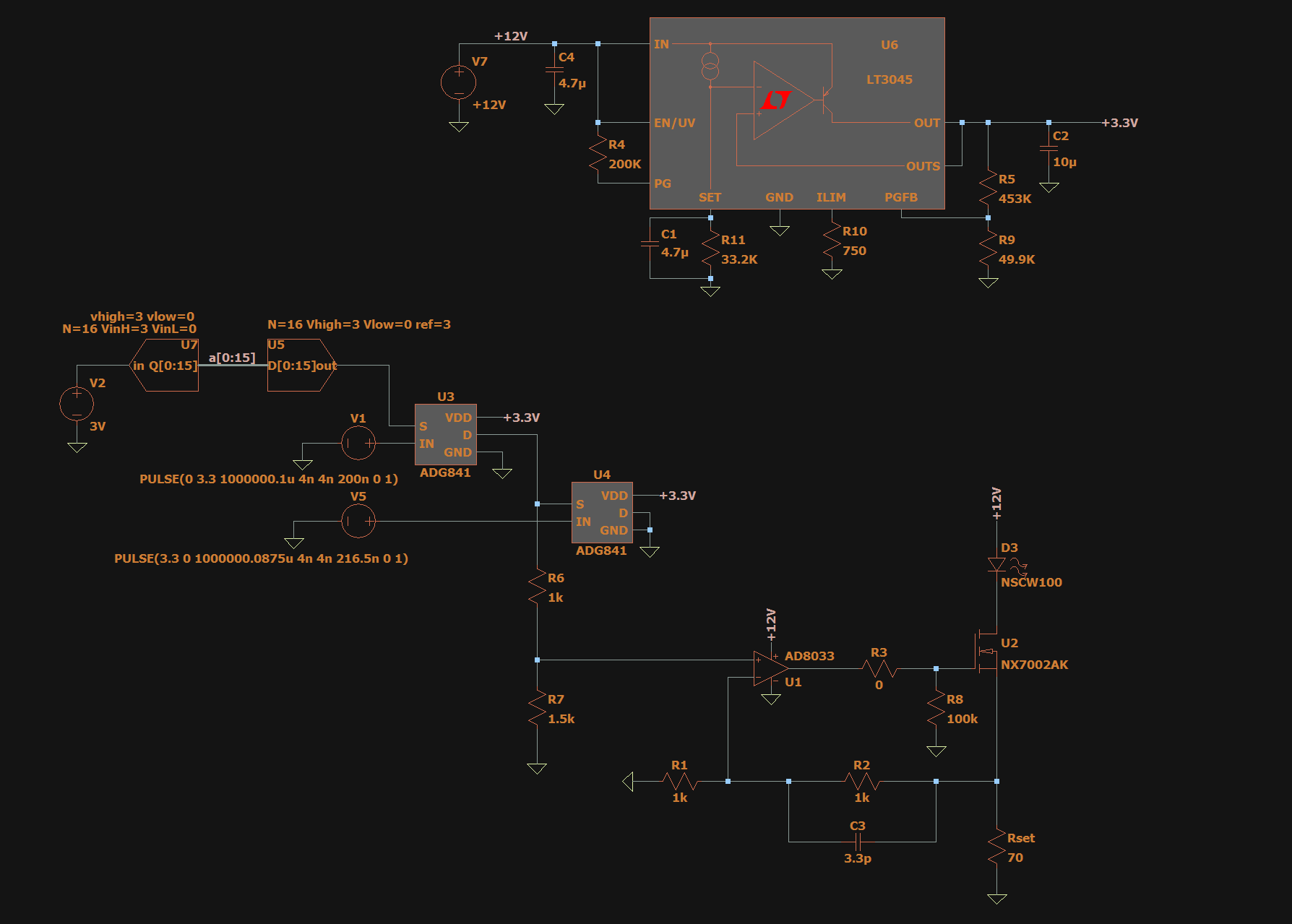
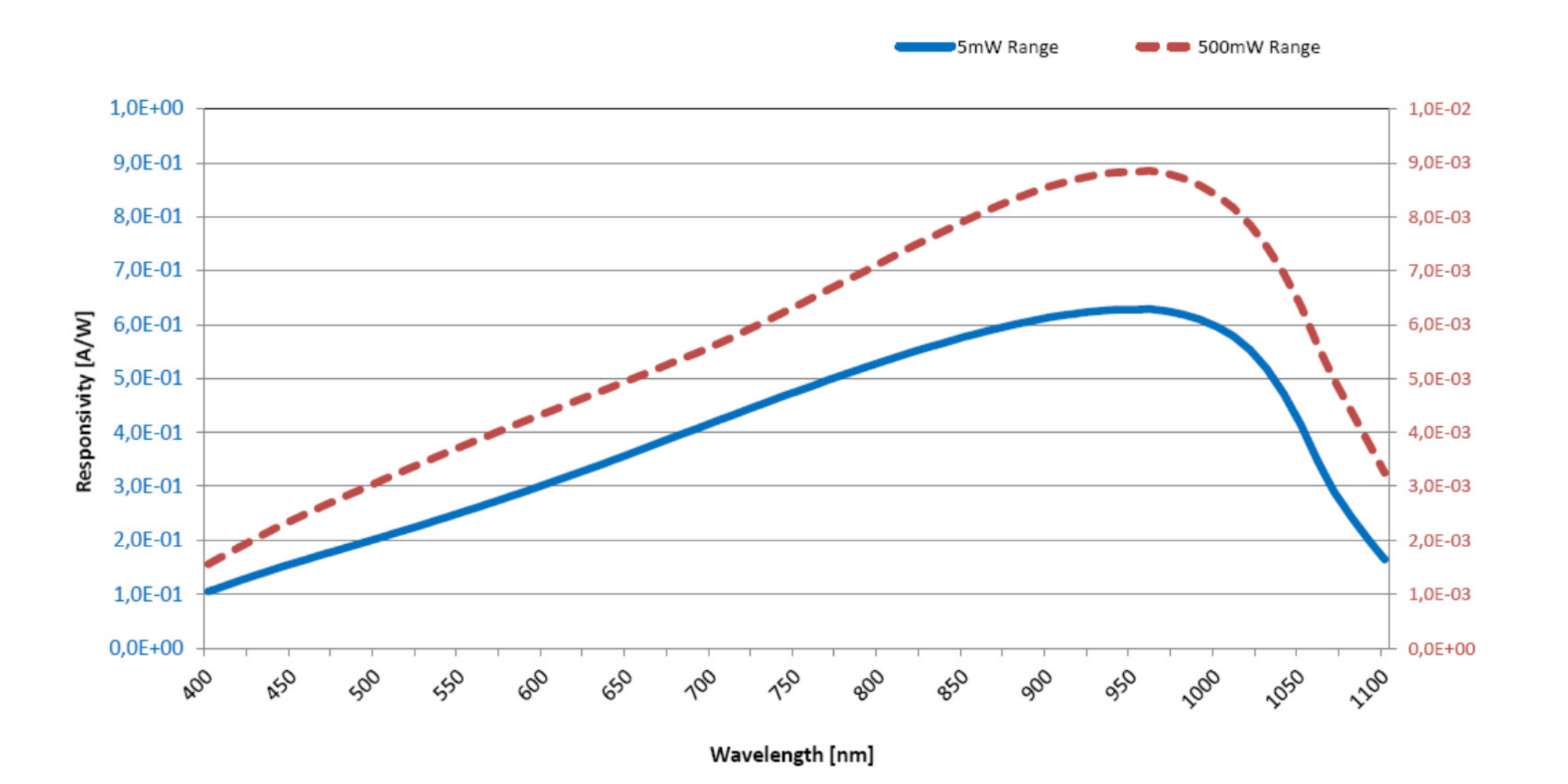
I am designing a current source that is going to control LED. With help of the DAC and microcontroller, I generate a voltage that goes to OP-amplifier, and afterward, I am opening my NMOS transistor. I have attached my schematic of the simulation below. I want to add a photodiode power sensor for the better accuracy of my circuit. Now my question is how could I simulate the photodiode relating to the luminosity power that my LED is emitting. Is it possible that I could connect these two in LTspice? I am new at LTspice and I would need it for my university project. I thought I could use an arbitrary behavior current source, using it as I would simulate temperature. My photodiode power sensor is S130C from Thorlabs. I would be thankful for any advice on how could I realize my problem.
-
\$\begingroup\$ I would put a 100k resistor Emitter to detector to simulate CTR of your optical path and devices then tune to suit the actual later. You may get ambient interference from fluorescent lights in the real world . \$\endgroup\$– D.A.S.Commented Mar 5, 2021 at 22:46
-
\$\begingroup\$ What are your proposed simulation input(s) to the power sensor? For a given fixed wavelength it could be just a VCCS with the control voltage representing the power. \$\endgroup\$– Spehro 'speff' PefhanyCommented Mar 5, 2021 at 22:50
2 Answers
Now my question is how could I simulate the photodiode relating to the luminosity power that my LED is emitting. Is it possible that I could connect these two in LTspice?
You can use nodes to carry information other than voltage or current, but LT spice still thinks that they are voltage or current. The way to do this is with b-sources which can handle different functions.
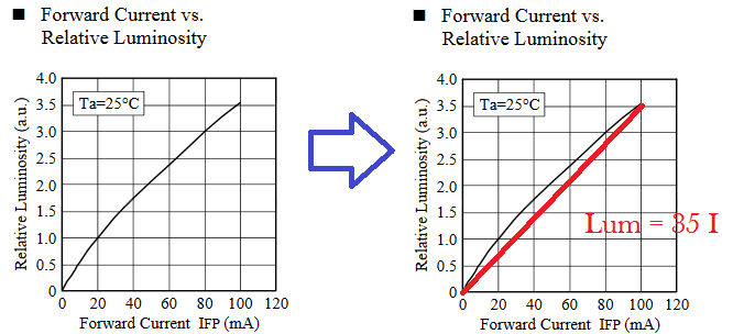 Source (modified by me): https://datasheet.octopart.com/NSCW100-Nichia-datasheet-22171761.pdf
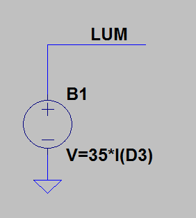
First model the diode (a first order polynomial fit with 35, if you want to get more accurate digitize the graph and fit it with a second order poly)
You can then use the luminosity with another model to model the photodiode, you would need to use
V(LUM)
in the second bsource for the photodiode. I would finish this but those equations would take a bit of solving and a lot of time. (and actually there is a bunch of luminosity to responsitvity equations that involve radiometry, so you need to know the distance between the sensors, and how much power is moving from source to detector which is the subject of chapters in books)
But that being said if you can come up with a function for the photodiode, you can use the signal from V(LUM) in the photodiode equation with a b source to come up with the photodiode voltage.
Obstruction simply means less current through the diode, so you could either add an element across the diode to simulate a resistive (dissipative) effect, or divert the current with another current source, controlled or not. The first method may require additional calculations, while the second might be easier in terms of setting a control voltage/current.
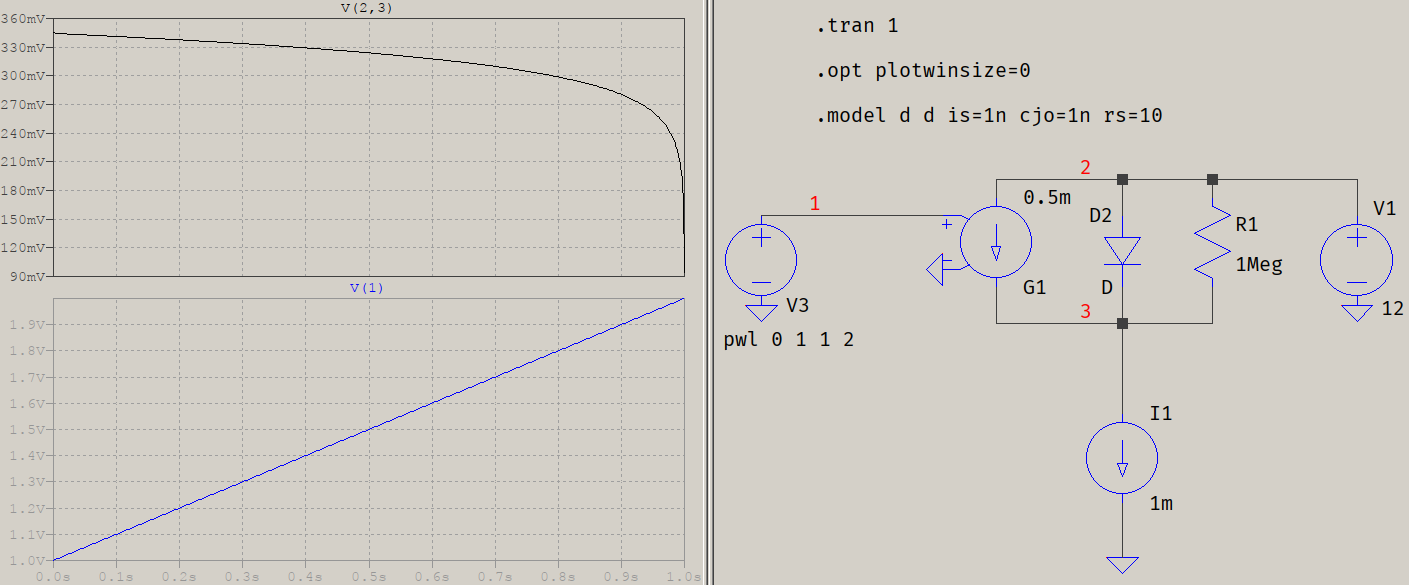
You have a constant current source, so the current through the whole circuit (ciode and parasitic) will be the same, only the diode will see less. Which means you can just model this on the same principle as a solar panel cell: a current source controlling the intensity of the light:
G1 is reversed because it's "stealing" current. I1 is meant to reproduce the constant current source, and V3 some variation of light (here a simple ramp from 1 V to 2 V). The values for the diode are from the master wet finger in the wind. This is just the principle of operation.
-
1\$\begingroup\$ BTW, if you just need a quantized value for your
V2, you can use a simple behavioural source with the appropriate formula. But if you need a quantized value for a dynamic signal, then theQuant16block might be easier to use, instead of two ADC+DAC. It also lets you specify what type of conversion to use:int(),ceil(),floor(), orround(). \$\endgroup\$ Commented Mar 5, 2021 at 23:33

