1
\$\begingroup\$

I have been given a prompt to design a 7 segment display using NOR gates. My understanding of the prompt (8.R) is:

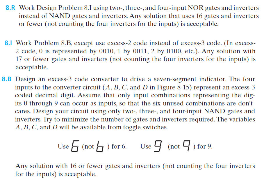
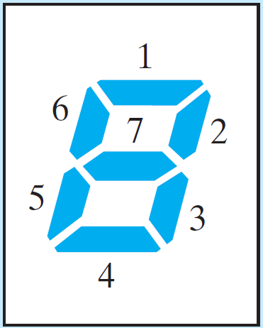
Design an excess-2 code converter to drive a 7 segment display. Design the display using two, three, and four input NOR gates and inverters. Any solution that uses 16 gates and inverters or fewer (not counting the four inverters for the inputs) is acceptable.

Prompt

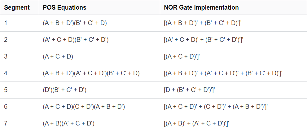
Using K-Maps, I have derived seven POS equations that I converted to NOR gates through double inversion.

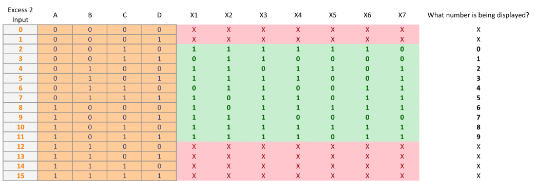
Seven Segment Display Truth Table

Segment POS Equations NOR Gate Implementation
1 (A + B + D')(B' + C' + D) [(A + B + D')' + (B' + C' + D)']'
2 (A' + C + D)(B' + C' + D') [(A' + C + D)' + (B' + C' + D')']'
3 (A + C + D) [(A + C + D)']'
4 (A + B + D')(A' + C + D')(B' + C' + D) [(A + B + D')' + (A' + C + D')' + (B' + C' + D)']'
5 (D')(A' + C' + D) [D + (A' + C' + D)']'
6 (A + C + D)(C + D')(A + B + D') [(A + C + D)' + (C + D')' + (A + B + D')']'
7 (A + B)(A' + C + D') [(A + B)' + (A' + C + D')']'

To reduce the number of gates, some are reused. These gates are (A + B + D')', (B + C + D')', and (B' + C' + D)'.

Afterward, my logic diagram looks like this: Logic Diagram
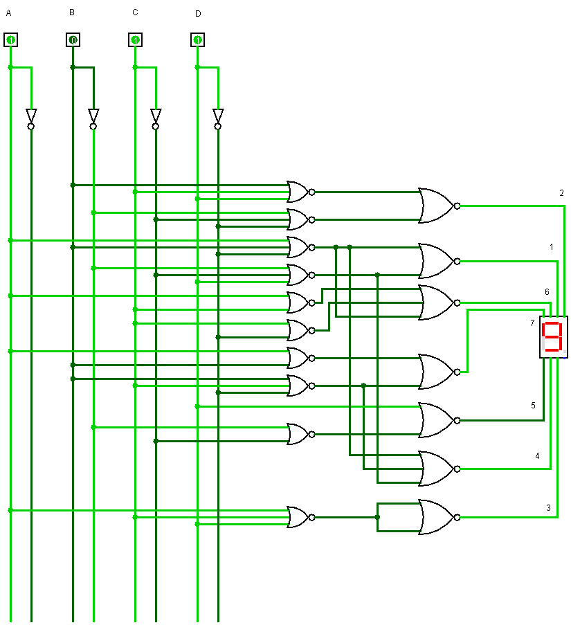
The Problem

Counting up the logic gates on my diagram (excluding the inverters from the inputs A through D), I count 17 gates. This does not satisfy the requirements of the prompt. Therefore, I am thinking I messed up somewhere along the way, either in:

  • Deriving POS gates from my K-Maps
  • Reusing shared gates

I'm lost as to what I could improve to reduce my gate count by one. Any ideas?

\$\endgroup\$
8
  • \$\begingroup\$ Do you use a LOW for an active LED drive? Or a HIGH? (From what I see glancing over the above, I'd say you could use either choice.) \$\endgroup\$
    – jonk
    Commented Mar 12, 2021 at 5:32
  • \$\begingroup\$ Examine this. \$\endgroup\$
    – jonk
    Commented Mar 12, 2021 at 7:26
  • \$\begingroup\$ Logic reduction to simple gates (NANDs and NORs, usually) is more of an art… you usually kick your formulas and factor them until you find a common part. This is one of the reason that FPGAs use LUT tables instead of gate arrays like the CPLDs do. \$\endgroup\$ Commented Mar 12, 2021 at 9:08
  • \$\begingroup\$ @jonk Thank you for your replies. I have tried to implement your solution, but it's not quite working out for me. Here's what I got when trying to display the number 4. I double checked that I followed your solution correctly, but I could be wrong. \$\endgroup\$ Commented Mar 15, 2021 at 5:48
  • \$\begingroup\$ @jonk How is throwing a schematic at someone supposed to help them understand the process of optimizing a design? \$\endgroup\$ Commented Mar 21, 2021 at 21:38

1 Answer 1

-1
\$\begingroup\$

Diagram1

Here is the correct implementation that yields 15 gates.

\$\endgroup\$
2
  • \$\begingroup\$ Please don't hand out homework solutions. Our approach here is to provide hints and make suggestions, so that the OP will learn how to solve such problems themselves. \$\endgroup\$ Commented Mar 25, 2021 at 12:00
  • \$\begingroup\$ @ElliotAlderson Apologies, I am the OP. I figured out the solution on my own. I simply had to go about selecting my K-Map POS equations in a better way that would reuse gates. As a previous commenter mentioned, deriving equations from K-Maps is kind of an art form, and that is what I learned as well. My original table has been updated to reflect the solution I found. i.imgur.com/zRmV7Nx.png \$\endgroup\$ Commented Mar 25, 2021 at 16:40

Your Answer

By clicking “Post Your Answer”, you agree to our terms of service and acknowledge you have read our privacy policy.

Not the answer you're looking for? Browse other questions tagged or ask your own question.