2
\$\begingroup\$

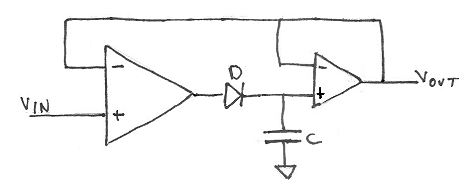
I have been looking into peak detector circuits for something I am designing and looking through Google, the common method seems to be this:

enter image description here

Quite simple really. But, I have an engineer at my work who isn't a fan of this circuit because he says an op amp will struggle to drive a capacitive load, which I know is a thing. So I built the circuit and have been messing around with capacitor values and different op amps, and I can't seem to get the op-amp to start oscillating as he tells me it will. I like this circuit for its simplicity, and surely if you are careful about component selection, these things shouldn't be much of a worry? The engineer has admitted that analog design isn't their strong point, but is still unsure of this circuit.

From what I have seen, it has been used widely (although maybe not so much anymore) and during my testing, it had no problem driving capacitors into the µF range (I tested up to 4.7µF) although I should only need a maximum of 1µF, so I would think this is fine.

I did a bit of looking into op amps and capacitive loads and sure enough, op amps can go into oscillation if trying to drive capacitive loads, and these can sometimes be small values. So why does it not seem to affect this circuit? Or does it, and I am just in fact not seeing it?

Just for clarification, I am not asking for alternative circuits, I just want to know why this configuration seems to be stable with a capacitive load.

\$\endgroup\$
3
  • \$\begingroup\$ Your diagram doesn't show any means of draining the capacitor. Surely you'll eventually want to reset? There's an initial bulk surge to charge the cap, so if the cap is large, consequence of limitations of op amp output might mean heating the op amp or missing the first n peaks. With modern high impedance op amp inputs and a good quality diode and a well chosen capacitor, once the bulk charging is done the op amp only needs to feed a small leakage current. This allows the capacitor to be small which in turn helps by limiting bulk charging current. \$\endgroup\$
    – K H
    Commented Mar 12, 2021 at 11:05
  • \$\begingroup\$ The capacitor has to be large enough compared to leakage current that a reading can be made before appreciable leakage occurs, so if you have a microcontroller checking it every 50ms you can get away with a much smaller capacitor than if it gets polled every 10s. I see Andy already addressed draining the cap, but I'd drain it with an NMOS(it goes in parallel to the cap not in series) and see just how small I could get that cap. In addition to the minimum capacitor size determined by leakage currents, there is a maximum capacitor size determined by the duration of the peak you want to detect. \$\endgroup\$
    – K H
    Commented Mar 12, 2021 at 11:23
  • \$\begingroup\$ @KH thanks for the comments. If you read my reply to Andy, I did mention using a MOSFET to drain the capacitor between readings or when needed. The diagram was just a basic one taken from online, it isn't the schematic I drew (laziness of redoing it on the schematic editor!) \$\endgroup\$
    – Curious
    Commented Mar 12, 2021 at 12:39

1 Answer 1

2
\$\begingroup\$

I just want to know why this configuration seems to be stable with a capacitive load.

It's a non-linear circuit that attempts to charge a capacitor when the input voltage exceeds the previously highest input voltage and, there is no basic problem here; it can't go unstable (as I suspect your engineer colleague thinks it will) because it's not a linear amplifier AND, the capacitor is only called into-action when a new high-peak of voltage arrives at the input. That occurs rarely and is of no consequence to stability.

There's a big difference between struggling to drive a capacitive load (which all op-amps suffer from to one extent or the other) and trying to remain stable in the presence of a capacitive load in a linear circuit. This rectifier circuit WILL NOT go unstable unless you have chosen an op-amp that cannot be used in linear unity gain situations (there are a few).

You do need a "light" pull-down resistor in parallel with the capacitor by the way.

\$\endgroup\$
6
  • \$\begingroup\$ Thank you. I had suspected that this wouldn't suffer, but being the junior engineer, I needed to have a bit more than a few practical examples before trying to bring this idea forward more. How would I know which value of resistor to have in parallel? \$\endgroup\$
    – Curious
    Commented Mar 12, 2021 at 9:40
  • \$\begingroup\$ Well, you do need to discharge the capacitor gradually over time or the circuit becomes a single peak detector for the rest of time; once the biggest peak has occurred, the output stays at that voltage and is never reset to allow the next biggest peak to register a new (but lower) value. I can't tell you what RC value because you haven't specified an application @Curious \$\endgroup\$
    – Andy aka
    Commented Mar 12, 2021 at 9:49
  • \$\begingroup\$ Decide what decay period you want for the peak detection and choose a resistor so that the time constant is appropriate. BTW the limiting factor for the peak detection will be the current that the op amp can supply, which is likely to be a few mA, so a 1uF capacitor will charge up at a few volts per millisecond. \$\endgroup\$
    – Frog
    Commented Mar 12, 2021 at 9:53
  • \$\begingroup\$ @Andyaka I was thinking of having a MOSFET in series so I can discharge the capacitor whenever I need to take a new reading. Is that wise, or should I use a resistor too? \$\endgroup\$
    – Curious
    Commented Mar 12, 2021 at 10:03
  • 1
    \$\begingroup\$ You’ll also need to consider the reverse leakage of the diode and the input resistance of the buffer, which will tell you the minimum value of capacitor you can get away with. \$\endgroup\$
    – Frog
    Commented Mar 12, 2021 at 10:12

Your Answer

By clicking “Post Your Answer”, you agree to our terms of service and acknowledge you have read our privacy policy.

Not the answer you're looking for? Browse other questions tagged or ask your own question.