1
\$\begingroup\$

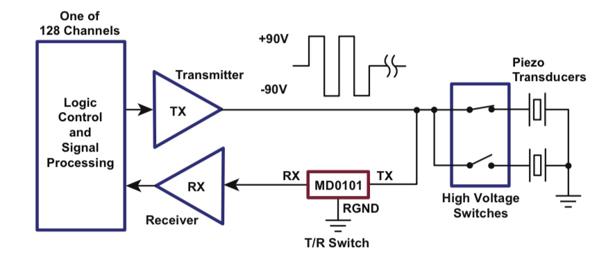
I want to set up an experiment exactly as given in this data sheet for the T/R switch that I recently bought (the MD0101):

enter image description here

Every pulser receiver circuit that I’ve found neglects to address what happens during the “receive” portion of the event, i.e., if you’re using a function generator that just pulls the output to ground after sending out a pulse train, how are you supposed to be able to sense any movement in the piezo transducer if both of its plates are grounded?

The only way this circuit would work is if the function generator immediately disconnected its channel after sending out the pulse train, correct?

\$\endgroup\$
4
  • \$\begingroup\$ Yes, I agree but, if the transmit driver was a current source then it should work. \$\endgroup\$
    – Andy aka
    Commented Mar 14, 2021 at 10:20
  • \$\begingroup\$ More generally, it is only required that the impedance of the piezo be low compared to the Tx. A more normal T/R switch is SPDT with the common terminal connected to the DUT. Then the Tx is out of the circuit during receive mode. \$\endgroup\$
    – 10ppb
    Commented Mar 14, 2021 at 15:22
  • \$\begingroup\$ @10ppb I couldn't find a single pulser receiver circuit with an SPDT T/R switch (although it would make perfect sense). I have only seen them used in antenna circuits. Undiscouraged, I still looked for an SPDT T/R switch for my application (Analog Devices was the only source I found: analog.com/en/products/rf-microwave/rf-switches/spdt-t-r.html) but I couldn't find a single one that could handle over 10 W (e.g., HMC784A) through it. \$\endgroup\$
    – Landon
    Commented Mar 19, 2021 at 2:28
  • \$\begingroup\$ There are high power spdt switches in the article your drawing comes from: digikey.com/en/articles/… \$\endgroup\$
    – 10ppb
    Commented Mar 19, 2021 at 4:28

1 Answer 1

1
\$\begingroup\$

Close... The Tx must stop the ringing faster than the expected echo return time. This is due to stored energy.

Thus the sequence is stop Tx, short circuit device, then open high impedance and unblock Rx which was shorted during Tx.

I once had exactly the same problem with a tiny servo motor with position feedback. I moved with a half-bridge to pull up or down V+ or V- until position error was zero. When null error was detected, it floated but the tiny stored inertia caused a small offset error to jump at turn off. So on my SCADA design, I had to send a command to short circuit my half-bridge (activate both drivers) for <<1ms to stop the motor aggressively and short-cct both supplies by V/DCR to stop the inertia of the motor then open both drivers to detect external forces. Your time duration will be much less and depends on BW of the resonator. My solution worked like a charm yet I had never heard of it before.

\$\endgroup\$
4
  • \$\begingroup\$ Ringing as in transmission line ringing? Is this because although everything is impedance matched in the circuit, there is an acoustic impedance mismatch between the transducer element and the water? \$\endgroup\$
    – Landon
    Commented Mar 14, 2021 at 8:35
  • \$\begingroup\$ So you short-circuit the ultrasonic transducer to discharge it because it charged up like a capacitor during the transmitting stage? \$\endgroup\$
    – Landon
    Commented Mar 14, 2021 at 8:36
  • \$\begingroup\$ Ringing including ringing in the transducer. \$\endgroup\$
    – user16324
    Commented Mar 14, 2021 at 13:24
  • \$\begingroup\$ All piezo electric crystals, MEMs and ceramic resonators have a stored energy in the motional capacitance with the series equivalent inductance of the domain walls. So like a spring mass motion, it must be stopped abruptly then allowed to float for echoes or external waves into a high impedance amplifier. \$\endgroup\$
    – D.A.S.
    Commented Mar 14, 2021 at 14:53

Your Answer

By clicking “Post Your Answer”, you agree to our terms of service and acknowledge you have read our privacy policy.

Not the answer you're looking for? Browse other questions tagged or ask your own question.