0
\$\begingroup\$

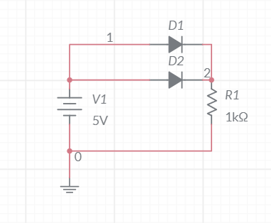
If we have this circuit:

enter image description here

The diode with the lowest forward voltage drop will conduct and turn on while the other will turn off and not conduct current.

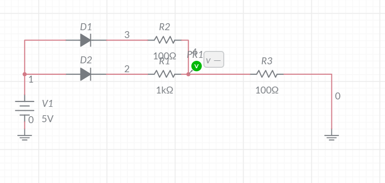
If I have this circuit:

enter image description here

Assuming the 2 diodes have the same voltage drop, R1 can be considered to be in parallel to R2 and that's how we solve those circuits.

However in the same case, what if the 2 diodes have different forward voltage drops? Say Vd1>Vd2 which assumption should I take into account?

\$\endgroup\$
7
  • \$\begingroup\$ You said it yourself: one diode will not conduct. \$\endgroup\$ Commented Mar 15, 2021 at 20:26
  • \$\begingroup\$ Ok thanks a lot.Doesn't it matter the resistor value of the branch with the high voltage drop diode is lower than the resistor value of the brance with the low voltage drop diode ? \$\endgroup\$
    – Miss Mulan
    Commented Mar 15, 2021 at 20:28
  • \$\begingroup\$ You'd need to solve the circuit, considering that the current must split, and the resistor voltage drop (V = IR) plus the resistor diode drop match. You may need to use a system of equations to relate all of the things happening simultaneously. \$\endgroup\$
    – nanofarad
    Commented Mar 15, 2021 at 20:32
  • \$\begingroup\$ If you show me how we do that in an answer i will accept it. \$\endgroup\$
    – Miss Mulan
    Commented Mar 15, 2021 at 20:33
  • \$\begingroup\$ @MissMulan Writing it up with the equations right now.' \$\endgroup\$
    – nanofarad
    Commented Mar 15, 2021 at 20:33

3 Answers 3

2
\$\begingroup\$

You'd need to solve the circuit, considering that the current must split, and the resistor voltage drop (V = IR) plus the resistor diode drop match. You may need to use a system of equations to relate all of the things happening simultaneously, such as the following:

Let \$V_x\$ be the voltage at the green probe, \$i_1\$ the current through D1/R2 (top branch), and \$i_2\$ through D2/R1 (bottom branch). I'll keep your assumption that the voltage drop of a forward-biased diode is constant. and furthermore, I will assume that the diodes are all forward-biased (and will check this assumption after solving).

We can relate the voltage drop between the 5V supply and Vx with the currents in the diode-resistor branches, and we can relate the voltage drop across R3 with the current in that branch (i.e. the sum of \$i_1\$ and \$i_2\$).

This gives us:

$$ \begin{align} V_x &= (i_1 + i_2)R_3\\ 5 - V_x &= i_1R_2 + V_{D1}\\ 5 - V_x &= i_2R_1 + V_{D2} \end{align} $$

This is a system in three equations and three unknowns, and can be solved using your choice of solution technique.

Once you solve it, you must verify that the diodes are, in fact, forward biased (i.e. \$5 - Vx\$ is greater than \$V_{D1}\$ and \$V_{D2}\$). If the assumption is violated, then that diode is actually not forward-biased, and no current flows in that branch; you'll set up the equations and solve them again under that revised assumption.

On the other hand, the constant-drop model is no good in the first schematic you have. The two diodes are in parallel, so their current must split according to the smooth I/V curves associated with each of them. The series resistors added to both branches in the second schematic make the approximation hold significantly better (but still not that well).

\$\endgroup\$
5
  • 1
    \$\begingroup\$ I agree with your equations, but I can't really agree with accepting the "constant forward voltage" model: Especially in the upper circuit it's clear that the model isn't sufficient to describe these circuits! Miss Mulan has to use better models! \$\endgroup\$ Commented Mar 15, 2021 at 20:42
  • \$\begingroup\$ @MarcusMüller At a quick glance, I feel that the resistor values may be adequate to make the approximation "good enough" to approximately model the circuit's rough behavior. For the kinds of currents I'd expect to flow, the voltage drops of R1 and R2 would vary more significantly than the logarithmic drop across the diode junction with respect to branch current. \$\endgroup\$
    – nanofarad
    Commented Mar 15, 2021 at 20:45
  • \$\begingroup\$ We're talking about the second schematic, right? (in the first, where the two diodes are actually in parallel, it's clear that the model breaks down, since both diodes will conduct.) \$\endgroup\$ Commented Mar 15, 2021 at 20:46
  • 1
    \$\begingroup\$ @MarcusMüller I'm talking about the second schematic -- I will add a note warning about the first. A quick sketch in falstad shows a decent error in the constant-drop model, but not one that completely breaks understanding of the circuit. \$\endgroup\$
    – nanofarad
    Commented Mar 15, 2021 at 20:48
  • 1
    \$\begingroup\$ Thanks you very much! \$\endgroup\$ Commented Mar 15, 2021 at 20:49
4
\$\begingroup\$

The diode with the lowest forward voltage drop will conduct and turn on while the other will turn off and not conduct current.

No, one diode will likely conduct more current than the other, but they will both conduct current.

Assuming the 2 diodes have the same voltage drop, R1 can be considered to be in parallel to R2

No, if the two diodes have the same voltage drop, the resistors will also have the same voltage drop. However, the fact that the resistors have the same voltage drop does not make them "in parallel".

However in the same case, what if the 2 diodes have different forward voltage drops? Say Vd1>Vd2 which assumption should I take into account?

If diodes had a fixed voltage drop (they don't - that is only an approximation) then, for each path, you would subtract that voltage drop from the total voltage across the diodes and resistors, and use Ohm's law to calculate the current in each path.

In reality, the current through a forward biased diode is nearly exactly exponentially related to the voltage across the diode. One can use a computer to solve for the current through, and the voltage across, each diode in the circuit. However, the solution technique generally involves finding successive approximations, and so is difficult for a human to calculate a precise answer by hand.


Addendum:

Why One Cannot Treat Resistors R1 and R2 in the Second Diagram as Parallel.

Suppose that

  • D1 and D2 are identical, and have a forward voltage drop of 0.7V
  • R1 has a value of 100\$\Omega\$
  • R2 has a value of 1k\$\Omega\$

If R1 and R2 were parallel, they could be replaced with a single resistor \$R_p\$ with a value of $$R_p=\frac{R_1R_2}{R_1+R_2} = \frac{100,000}{1,100} = 90.91\Omega$$

and the circuit would look like
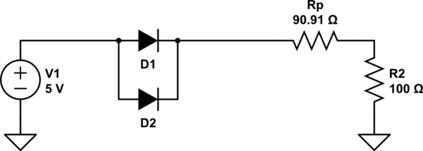
schematic

simulate this circuit – Schematic created using CircuitLab

With this arrangement, the current in each diode D1, and D2 would be identical.

However, with the actual circuit, again, assuming each diode is identical and has a voltage drop of 0.7V, we can replace the diodes with voltage sources, like this:
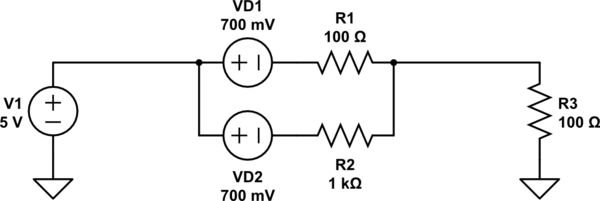
schematic

simulate this circuit

With this arrangement, 2.048mA flows through D1 and 20.48mA flows through D2.

Conclusion, R1 and R2 cannot be replaced by a parallel equivalent resistor, because it changes the behavior of the circuit.

\$\endgroup\$
5
  • \$\begingroup\$ "No, if the two diodes have the same voltage drop, the resistors will also have the same voltage drop. However, the fact that the resistors have the same voltage drop does not make them "in parallel".I don't say there are in parallel but it is a good aproximation to treat them as parallel to solve our circuits and the results of the simulation and this way agree pretty well. \$\endgroup\$
    – Miss Mulan
    Commented Mar 15, 2021 at 20:59
  • \$\begingroup\$ You said "R1 can be considered to be in parallel to R2", If that were so, you could replace them with a resistance (R1*R2)/(R1+R2). You can't do that. Or rather, if you do, do that, you will get an incorrect result. \$\endgroup\$ Commented Mar 15, 2021 at 21:03
  • \$\begingroup\$ Yes you can do that.And I have checked it with multisim it approximates it well enough. \$\endgroup\$
    – Miss Mulan
    Commented Mar 15, 2021 at 21:06
  • \$\begingroup\$ Sigh. No. Try it with diodes that are used for very different purposes. Use a diode rated for 10A in one case, and a diode rated for 1A in the other. (Actually it is saturated reverse leakage \$I_s\$ that is important, but it is likely that these two diodes will have different values of this parameter). If the diodes are in parallel, and one diode has an \$I_s\$ that is 10 times that of the other, one diode will conduct 10 times the current as the other. However, in your circuit, one resistor is 100\$\Omega\$ and the other 1k\$\Omega\$. You will get different currents than the parallel assump. \$\endgroup\$ Commented Mar 15, 2021 at 21:13
  • \$\begingroup\$ I will add a worked out example to my answer to show why you cannot treat the two resistors as being in parallel. \$\endgroup\$ Commented Mar 15, 2021 at 21:16
0
\$\begingroup\$

Assuming the 2 diodes have the same voltage drop, R1 can be considered to be in parallel to R2 and that's how we solve those circuits.

Can't do that. That assumption comes from a "constant forward voltage" model of the diode, which is too much of a simplification to be useful when you have multiple in parallel.

The diode with the lowest forward voltage drop will conduct and turn on while the other will turn off and not conduct current.

Also, same model of a diode either not conducting or conducting and having a constant forward voltage drop.

That model is OK if you only want to model rectification, but it's totally insufficient for modelling circuits where multiple diodes are in parallel. Both will conduct.

You need to take the usual exponential current-voltage relation, at the very least, to model these circuits.

\$\endgroup\$
4
  • \$\begingroup\$ Marcus Muller it is a good approximation though.Solving diode circuits using the VI curve of the diode is just too complicated for a human. \$\endgroup\$
    – Miss Mulan
    Commented Mar 15, 2021 at 20:42
  • \$\begingroup\$ No, my whole point is that it's not a good approximation here. It simply doesn't work – the results you'd be getting have nothing to do with how the circuit would behave in reality. I'm human, and so are all others that studied EE with me, and we all learned more complex diode models. You can, too, and probably should (and will). The circuits you have look like the "easy" entry-level exam questions we had to solve for our "electronic circuits" exam with the exponential diode models in the second semester, and you strike me as rather clever, so I'm sure you'll manage, somehow. \$\endgroup\$ Commented Mar 15, 2021 at 20:44
  • \$\begingroup\$ The simulation in multisim matches very well with the results I have found using the costant voltage drop method:).I agree for many diodes the results may differ a lot but form a small number of diodes it is good approximation. \$\endgroup\$
    – Miss Mulan
    Commented Mar 15, 2021 at 20:47
  • 1
    \$\begingroup\$ I don't know which diode model you use in multisim, but I'm 100% sure multisim won't tell you that in the first of your two schematics, only one diode conducts. \$\endgroup\$ Commented Mar 15, 2021 at 20:48

Your Answer

By clicking “Post Your Answer”, you agree to our terms of service and acknowledge you have read our privacy policy.

Not the answer you're looking for? Browse other questions tagged or ask your own question.