6
\$\begingroup\$

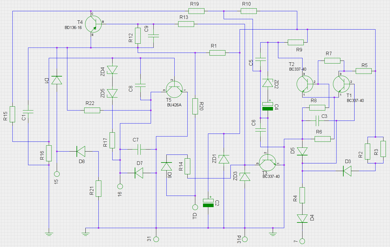
I have an old ignition module from a 1978 W116 model Mercedes-Benz, and I'm trying to "reverse engineer" it. The original circuit diagram is not available to mere mortals, so I have made one based on the PCB itself. I believe it is, beside being ugly, electrically correct. Thus far I have identified all resistors, caps and transistors (bar one). What I have a huge problem with are the diodes, and any help would be appreciated.

Schematic: Schematic

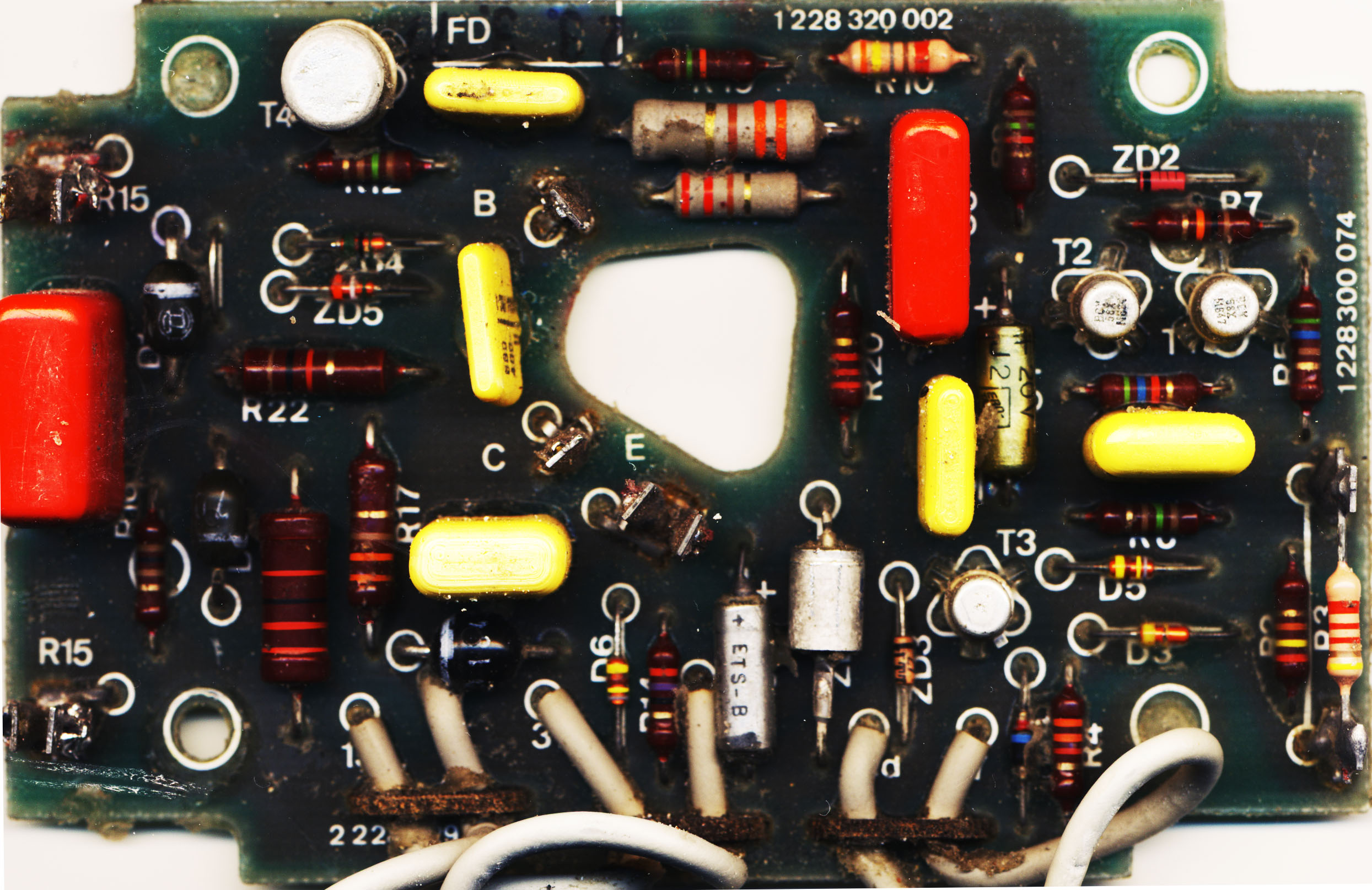
PCB Layout: PCB layout

The known diodes are: ZD1 - 6.8V Zener (5 Watt?) ZD2 - 2.7V Zener ZD3 - 27V Zener

ZD4, ZD5, D1 to D8 are unknown. ZD4/ZD5 are not shorted, but I'm getting nowhere with these with my 30V power supply, so they're probably rated above >30V. D3, D5 and D6 are fried.

D4 is just beside R4. The two left-most black diodes are D1 and D8 (both marked "703"), the one underneath them is D7 (marked "1849" and "714"). The missing T5 transistor is a TO3 packaged power transistor marked "1120008" and "7/32". I haven't cracked this one myself, but have been told a BU426A is a direct replacement for it. T1 to T3 are BCY58IX, T4 is a BSV15-16K.

The power supply is a standard 12V car battery.

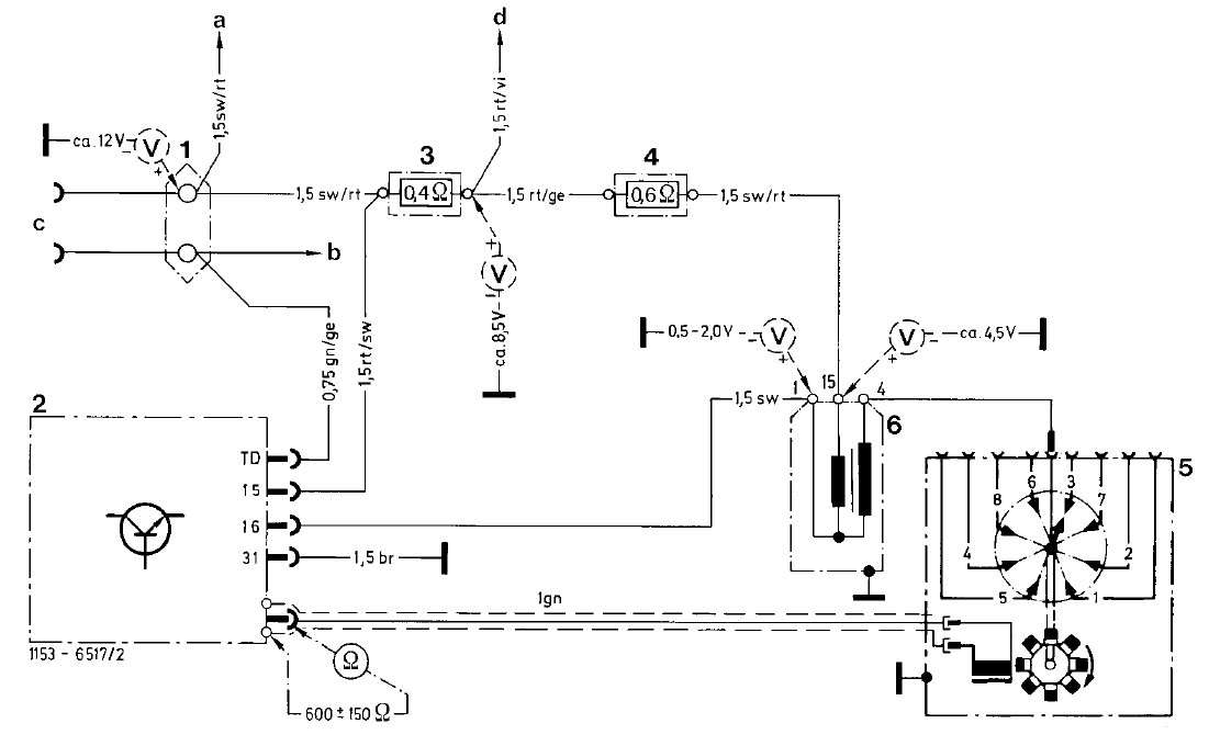
Edit: The entire ignition circuit looks like this: enter image description here (higher resolution)
\$\endgroup\$
3
  • \$\begingroup\$ The entire ignition circuit looks like this: link \$\endgroup\$
    – ptashek
    Commented Jan 18, 2013 at 2:19
  • \$\begingroup\$ Just in case anyone's not aware, a 12V car battery will tend to run about 13-14V when engine is running (if that is of any help). \$\endgroup\$
    – Shamtam
    Commented Jan 18, 2013 at 2:33
  • \$\begingroup\$ Make that schematic easier to read, and it might be possible to infer what the components are, or at least what might be a suitable replacement, by their function. See Rules and guidelines for drawing good schematics. \$\endgroup\$
    – Phil Frost
    Commented Jan 18, 2013 at 2:38

2 Answers 2

2
\$\begingroup\$

Partial answer : for any diode with yellow/brown/yellow/grey bands, 1N4148 is a pretty safe guess! I see at least two - D5 and D6.

D3 I can only see a yellow band - aka "4". Is there any sign on the solder side that it is a replacement? If so, 1N4148 may be OK, otherwise keep looking. Possibly 1N914 though the spec is so similar to 1N4148 (they are often interchangeable. Just checked in a Philips databook : 1n4148 handles 200ma, 1n914 only 75ma; other specs identical) I don't see any reason to use both.

Can you get better photos esp around ZD4,5? They look colour coded but I can't make them out. I suspect they may be fried, rather than >30V.

\$\endgroup\$
3
  • \$\begingroup\$ Brian Drummond: D3 has only a single yellow band, and there are no other markings on or around it. It has definitely been on the PCB from new - no traces of re-soldering, and the whole PCB was factory sealed with a silicone gel. ZD4 has a green cathode marker, and two bands - black and green. ZD5 has an orange cathode marker, and also two bands - white and green. Phil Frost: I'll see what I can do about making the schematic better quality. Would a parts list be of assistance? link \$\endgroup\$
    – ptashek
    Commented Jan 18, 2013 at 12:35
  • \$\begingroup\$ Then I suspect D3 is different for a reason... ZD4 : 5 0 5 ... 50V (non-standard) 5%? ZD5 : 3 9 5 ... possibly 39V (standard) 5%. This is a ropey diagnosis (unless the black band is really brown, 51V) Worth checking with a higher voltage supply and a fairly high value resistor. \$\endgroup\$
    – user16324
    Commented Jan 18, 2013 at 12:42
  • \$\begingroup\$ It is positively black and green. The question of what D1, D7 and D8 are remains, but I suspect they're just standard rectifiers. \$\endgroup\$
    – ptashek
    Commented Jan 18, 2013 at 17:44
3
\$\begingroup\$

To answer my own question, in case others are looking for this information:

  • D1, D3, D4, D5, D6 and D8 are 1N4148
  • D7 is 1N4003
  • ZD1 is 1N5342
  • ZD2 is BZX79-B2V7
  • ZD3 is 1N5361
  • ZD4 is 1N5366
  • ZD5 is 1N5369
  • T5 is BDW42G, or similar

Updated schematic available at https://www.circuitlab.com/circuit/5ag5z6/w116-ignition-control-circuit/

\$\endgroup\$

Your Answer

By clicking “Post Your Answer”, you agree to our terms of service and acknowledge you have read our privacy policy.

Not the answer you're looking for? Browse other questions tagged or ask your own question.