1
\$\begingroup\$

I would like to interrupt a program when a key is pressed on a keypad, and figure out which key has been pressed. I do not care much for ghosting effects, this is supposed to be operated with one finger.

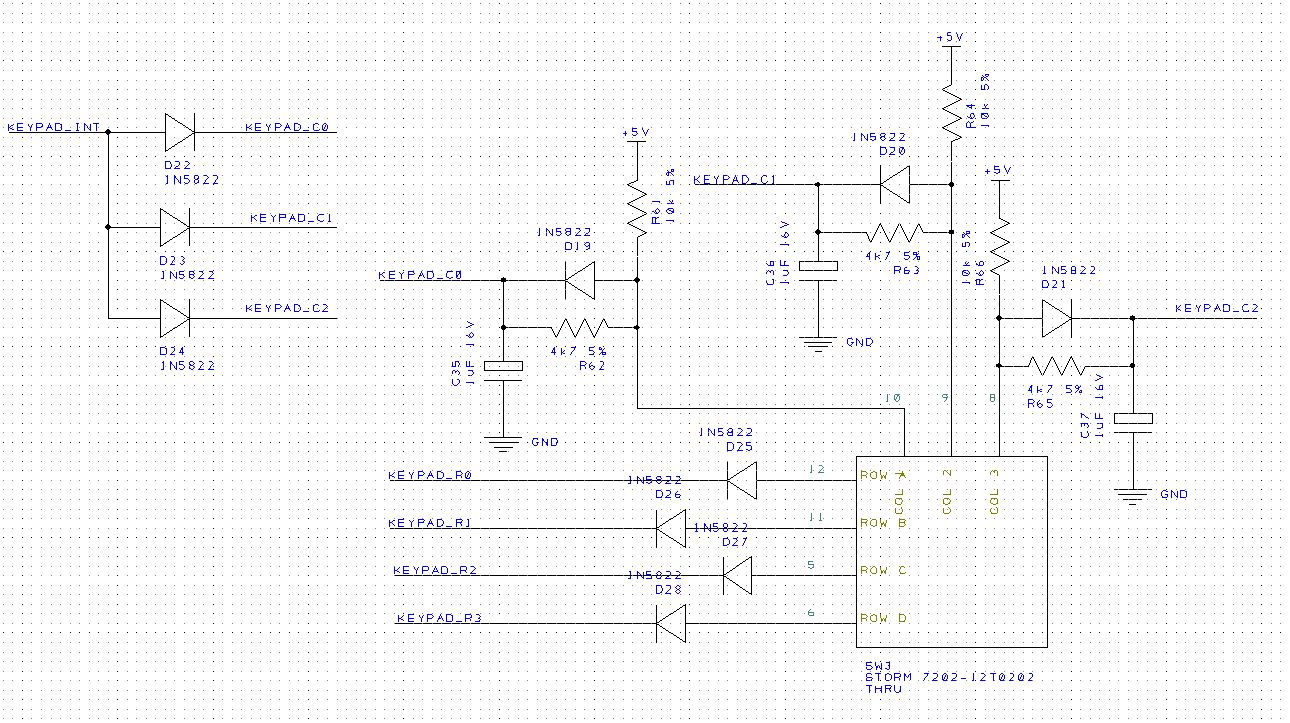
I came up with the following schematic, and I would like to know if this is going to work. enter image description here

Normally, this circuit protects against shorts from wrong output configurations. It provides 15Hz debouncing, and a common interrupt pin.

Note the KEYPAD_INT net is connected to D13 on an Arduino Mega, which is connected to a LED. I assumed this is not an issue since the ~100k input pullup is not enough to light it, and pushing a key will always force ~0.3V on this pin.

The columns are all inputs, built-in pull-up removed.

  • In sleep mode: all rows are driven LOW. When a key is pressed, KEYPAD_INT is driven low and a pin change interrupt is generated.
  • In ISR: all rows are high-Z, and for each row, drive it low and loop on each column until a low is detected. If none detected, it's a key release.
\$\endgroup\$
3
  • \$\begingroup\$ I could not find a circuit online combining both interrupts and debouncing, so this post should help others trying to do the same. \$\endgroup\$
    – user42875
    Commented Mar 19, 2021 at 15:17
  • 1
    \$\begingroup\$ Your large RC time constants for debouncing mean that some processor inputs will have very slow rise times. That can be problematic for some types of input pins. You also added a lot of extra components when this could normally be done in software. This might be a good solution for you but I don't think it is a good solution in general. \$\endgroup\$ Commented Mar 19, 2021 at 15:46
  • \$\begingroup\$ It might work but is sub-optimal for cost and noise-induced slow-rising multiple edges. and 15 Hz debounce is excessive even for clunky switches. \$\endgroup\$
    – D.A.S.
    Commented Mar 19, 2021 at 20:52

2 Answers 2

1
\$\begingroup\$

This isn't a good approach; focusing on a narrow section (the keypad itself) limits you from seeing higher-level solutions.

The better and more traditional overall approach, is to run the keypad as its own task. Either get a peripheral that does scan and debounce itself (then I2C or SPI to read once in a while), or run a timer interrupt to do the scan and read on the MCU.

Doing it on the MCU, you need to integrate your own debounce, of course. A typical system might do:

  • Set a given column as active, clear the others (use a diode type switch matrix).
  • Wait a modest delay: at least the propagation delay of the GPIOs (for AVR, a few CPU cycles; trivial in C, but worth being aware of in ASM), and any additional delay in case analog filtering has been applied.
  • Read the row bits (use external, or enable weak-pull-up resistors) and sore in an array.
  • Repeat for a full scan (every low-100s Hz; a ~kHz heartbeat timer is typical).
  • To implement debounce, have an array of bytes (or packed nibbles if you're short on RAM), one for each key; for each scan that returns a '1', increment the counter up to some maximum/limiting value; for each '0', decrement until zero. When the count equals max, set the output bit; when zero, clear the output bit.

Thus an indeterminate and noisy input does not change the detected value (or takes much longer to change), and the minimum delay for an input is scan rate / max count.

For press (edge) detection, compare previous to current value of the respective bit in the output array (you might want to keep a copy of previous inputs to enable this). For press-and-hold, make a counter, similar to the debounce timer, but the count is reset immediately on release, and it either triggers once on passing the desired count (and continues counting up to some irrelevant max, or perhaps looping on reaching some further count to make a press-and-repeat function).

The program in general should be an infinite loop that performs a sequence of actions, then waits for next heartbeat (which can then run a CPU sleep() to save power, if that's relevant); a discrete-time sampled state machine.

This may or may not be readily adaptable to the rest of your program as-is, but it's a good archetype in general for interactive programs; understand the concept of threading, what a thread is, how to sequence and communicate between them, etc. (namely: an interrupt is probably the most basic example of a thread). Maybe you run the matrix scan process in its own thread, and synchronize a copy of the outputs into the main thread, and maybe that's "thread" as in part of the timer interrupt, maybe it's another task in main() itself, whatever.
\$\endgroup\$
0
\$\begingroup\$

It depends if you want exclusive button reads or any combination.

You can use the data (or its inverse to trigger IRQ) then MASK the IRQ until no button is pressed and debounce the switch in S/W. Discrete or a 9-pin 8R-array may be used with a PISO.

I simulated a 4 kHz Clock and 250 Hz sample rate for 16 buttons. 4 may be left out.

One way is the traditional matrix read using 3 clock ports from uC and 1 serial data port.

There are ways to simplify this further, maybe.

IF you have trouble finding a non-blocking debounce routine you could always old-school put a cap across every switch with 1M*10nF=10ms that holds up more than the 5ms bounce time (typ) and then the cycle time of 4ms will capture on the 1st instant even if pressed for only 1us. Otherwise in S/W, you are just looking for 2 consecutive states to validate the change... More if you want to slow down the response time for changes. But n-key rollover is possible. Make or IRQ service routine as short as possible.

\$\endgroup\$

Your Answer

By clicking “Post Your Answer”, you agree to our terms of service and acknowledge you have read our privacy policy.

Not the answer you're looking for? Browse other questions tagged or ask your own question.