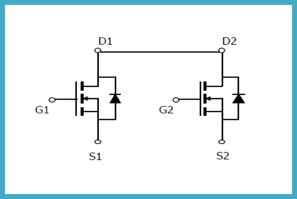
I'm learning the basics of MOSFETs and came upon these common-drain, dual MOSFETs in single package, AFN8205:
It seems they are used for some specific applications (e.g. load switch) as noted by manufacturer. one of its common application would be the switch for DW01 battery protection IC. (the left portion of circuit containing the TP4056 charger are not considered in this question):
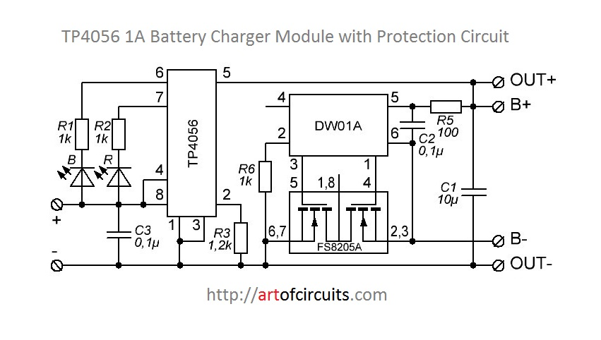
I had some problems understanding why the the 2 MOSFETs are used symmetrically and how they would turn on at all in this specific circuit. I tried to solve the circuit for the case for when the 2 MOSFETs are turned on for normal operation of the load (no overcharge nor over-discharge).
Both MOSFETs gates charged by control circuit:
In this case the GND of the battery should be connected to GND of the circuit. the current should flow through both MOSFET while they are ON so the internal diodes are not dropping voltage and wasting energy.
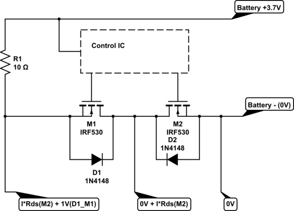
simulate this circuit – Schematic created using CircuitLab
- The right MOSFET turns on, because the gate voltage, Vgs (from the control circuit), is bigger than 0V of the source or the battery's negative pole (assuming the gate threshold is reached).
- The voltage at the common-drain would be ~0, equal to battery's negative pole and a tiny value considering the current flowing through Rds of the MOSFET. the Rds is <50 milli ohm for this particular MOSFET.
- The load which is turned on by now because of the internal diode of the left MOSFET, and is getting a voltage of ~0+1V because of the forward drop of the left MOSFET's diode.
- The left MOSFET turns on because of the assumption that the Vgs would be greater than threshold and ~1V of the source.
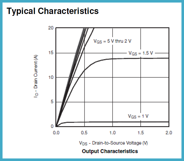
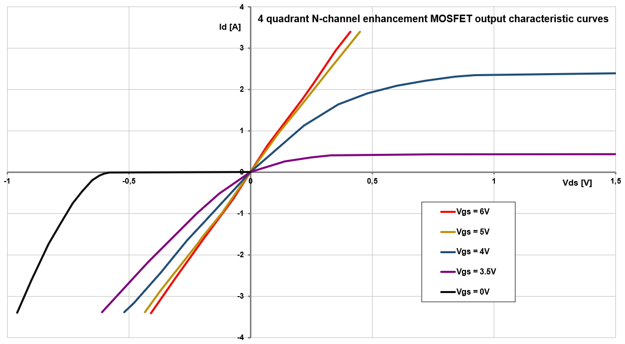
Here comes the problem. why the left MOSFET turns on when its drain-source voltage is "-1V"? the MOSFET only turns on when the drain source voltage is above a limit:
So, what's wrong?

