12
\$\begingroup\$

I'm new to electronics and am trying to make a night vision circuit. A similar question has been asked before, but with priority on efficiency. I want to control a 700mA-1000mA IR LED using a 5v input and an ESP8266 microcontroller as part of a night camera project. The LED should be able to be switched on/off from the MCU and will be off most of the time.

One solution is to use a dedicated LED driver / constant-current power supply, which is expensive (e.g. this LED driver for $7+shipping). Another solution is to use a single high wattage resistor, which is very inefficient. See:
How to drive high powered LEDs as efficiently as possible
How to drive high power LED and Arduino by the same power source?

I'm looking for a method of driving the LED using components that I can get cheaply (typical Arduino hobbyist components - a quarter watt resistor multipack, a transistor multipack (e.g. with BC337 and 2N2222 NPN transistors), buck/boost converters, the microcontroller itself).

LED specifications
These LEDs: https://www.aliexpress.com/item/32810764742.html
Forward Voltage: DC1.4-1.6V
Forward Current: 700-1000mA

Simple resistor method
My first thought is to use a current-limiting resistor. Then, from R=V/I we get R=5/0.7=7 ohms. From P=IV we get P=0.7*5=3.5 watts. I only have quarter watt resistors (and 3.5 watts sounds like a lot of power to dissipate), so this solution is not desired.

2-transistor method
I read about a method of limiting current using 2 transistors (schematic attached below).
Source 1 http://www.physics.unlv.edu/~bill/PHYS483/current_lim.pdf
Source 2 https://www.homemade-circuits.com/universal-high-watt-led-current-limiter/

This would satisfy my requirements of being a cheap solution and using simple components. I have BC337 and 2N2222 transistors. I think the BC337 can handle 800mA, with hFE being 100-630 (info for BC337 here). In the sources, they use an hFE value of 30. How do I know what value to use?

Questions

  • How to choose hfe?
  • What values should be used for R1 and R2?
  • How much power will the BC337 transistor need to dissipate?
  • Is the sensitivity to temperature tolerable? (e.g. 0-30 celsius)
  • The ESP8266 can output a PWM signal. Would this be useful for the circuit?

Here is my attempt at a schematic. This doesn't yet incorporate switching using 3.3v logic from the ESP8266.

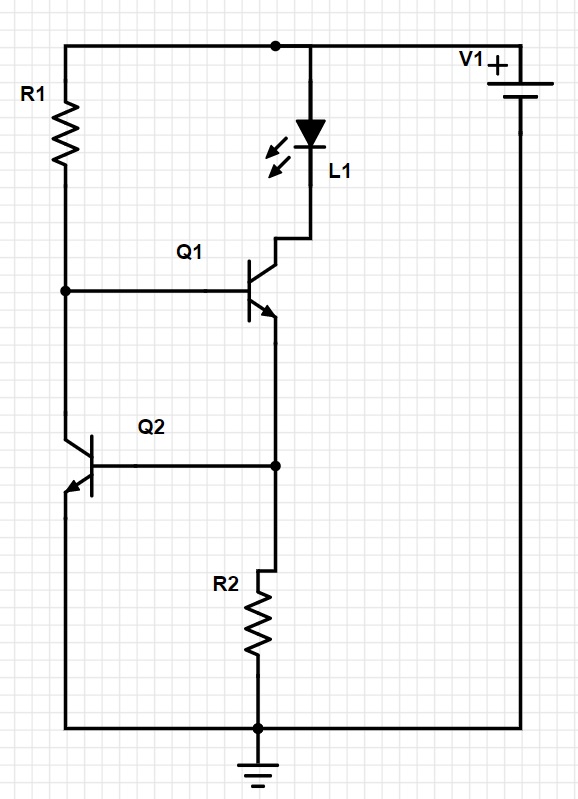
2 Transistor current-limiter

\$\endgroup\$
5
  • 3
    \$\begingroup\$ By efficiency what do you mean? Energy saving, low cost ? \$\endgroup\$
    – user263983
    Commented Apr 16, 2021 at 19:32
  • 1
    \$\begingroup\$ maurera, read here for how to design your given circuit. \$\endgroup\$
    – jonk
    Commented Apr 16, 2021 at 20:12
  • 2
    \$\begingroup\$ The resistor and transistor versions will dissipate pretty much the same amount of power. Neither one will win any efficiency award. If you have a PWM output available, it may make sense to use a slighly more complicated circuit and drive it with a PWM output from your micro. Basically a DIY fixed duty cycle buck converter. \$\endgroup\$
    – user57037
    Commented Apr 16, 2021 at 21:01
  • 1
    \$\begingroup\$ @mkeith - ok, this makes sense. I guess I would try to set the voltage through pwm to be equal to the forward voltage of LED + voltage drop of transistor (+ some buffer?). Then there would be less power to disapate, since P=IV and V would be lower? \$\endgroup\$
    – maurera
    Commented Apr 16, 2021 at 21:42
  • 2
    \$\begingroup\$ Yes. The "buffer" would be taken up by a resistor. Let's say the buffer is 1V. Then 100 Ohms will give you 10mA, and 10 Ohms will give you 100mA, and 1 Ohm will give you 1000mA, etc. So you could use, whatever, 1.5 Ohms or something to eat up the buffer. But the PAM2804 looks like a good option also. \$\endgroup\$
    – user57037
    Commented Apr 16, 2021 at 21:48

4 Answers 4

15
\$\begingroup\$

XY problem.

Your best efficiency solution from a power and cost point of view to drive a 1A LED load is to use a LED driver IC. There are many to choose from; the Diodes Inc PAM2804 seems likely to meet your needs. It supports PWM dimming. These chips are very inexpensive (about 15 cents Digi-Key price, half that in volume.) You could drive up to 3 of your IR LEDs in series with this chip since its sensing overhead is only 100 mV.

And if you think 15 cents is 'expensive', consider the thermal and efficiency issues you won't have to solve by using this IC, and their cost if you didn't use it and went linear. Way more than than 15 cents.


Regardless of the drive method you choose, there's an issue with using PWM chop to control dimming: this can interact with your frame capture, causing strobing. You will not be happy with the result if you use straight PWM: your image will have horizontal bars in it due to the interaction of sensor's rolling-shutter and the LED's pulsing light. This effect is the bane of videographers everywhere, and I'm sure you don't want that in your night-vision camera.

Instead, consider using a DC control method to modify the LED current. How to do that? The easy way is to use a current DAC like the Maxim DS4432. This device is I2C controlled, and can source or sink current to any node. It's kind of like a digital pot (another method to consider), but uses current, making it way more flexible. It's tiny. At about $1 Digi-Key, it might be a bit spendy. Microchip makes I2C digital pots that are about 50 cents Digi-Key.

A more involved, but cheaper way is to use the ESP8266 PWM output, and filter that to make a PWM-controlled current source to tweak the drive. This would mean an op-amp and a transistor and some passives. You might even be able to do it with just transistors, as a modification of your current source you're proposing.

Still another way is to choose an LED driver that accepts voltage dim control, like the MPS MP2410A. Then take the PWM and use a passive low-pass to create a dimming signal. Use a high-frequency PWM to minimize ripple and component size. The MPS part is definitely more expensive than the PAM2804 however.

\$\endgroup\$
10
  • 3
    \$\begingroup\$ That PAM2804 looks like it will do the job nicely. \$\endgroup\$
    – user57037
    Commented Apr 16, 2021 at 21:05
  • 2
    \$\begingroup\$ Thanks for this suggestion! 15 cents is certainly cheap - it's just $20 USD shipping to Canada that makes it expensive. I'll have a search on aliexpress for your suggestion of "LED driver IC". In my original post "expensive" referred to something like this for $7 - ledsupply.com/led-drivers/… (I'll clarify that in the original post) \$\endgroup\$
    – maurera
    Commented Apr 16, 2021 at 21:58
  • 1
    \$\begingroup\$ You can sometimes request samples. But, yes, ordering onesey-twosies of anything can get expensive, fast. \$\endgroup\$ Commented Apr 16, 2021 at 22:04
  • 1
    \$\begingroup\$ @Maurer try digikey.ca, I see CAD0.74 for the part and CAD8 shipping (for under-$100 order) \$\endgroup\$ Commented Apr 17, 2021 at 15:15
  • 1
    \$\begingroup\$ It might be worth pointing out that as the Maxim DS4432 has a maximum output current of 200 μA, more components, to make a DC-DC convertor, will be needed, so the cost would not be just $1. \$\endgroup\$ Commented Apr 17, 2021 at 19:09
10
\$\begingroup\$

I read about a method of limiting current using 2 transistors (schematic attached below).

All linear solutions, resistor or whatever, will have the same efficiency.

If you run the LED at 1A, it will draw 1A from 5V, so that's 5W. If there's 1.6V across the LED, then there will be 3.4V across the current regulator (whatever it is) so the LED will get 1.6W and the current regulator will burn 3.4W as heat.

You could put two LEDs in series for a total of 3.2V and use a lower value resistor. So you use more power in the LEDs, and waste less in the resistors.

Or you could get a switching LED driver.

\$\endgroup\$
2
  • 1
    \$\begingroup\$ Thanks for the response. This is succinct and explains how there's no getting around the issue with transistors / resistors. Makes sense. \$\endgroup\$
    – maurera
    Commented Apr 16, 2021 at 22:16
  • 2
    \$\begingroup\$ Yeah it's pretty unforgiving lol. If you use a linear solution, all you get to choose is whether you cook an delicate part that doesn't like heat, like a semiconductor, or a dumb resistor that doesn't care that much. If you want more efficiency, either add more LEDs in series, or use a switcher. \$\endgroup\$
    – bobflux
    Commented Apr 16, 2021 at 22:50
4
\$\begingroup\$

You have too many questions in one post, but I'll try.

You calculated the resistor dissipation as if it was the only load connected to 5V supply. The LED will drop about 1.5V so the resistor would not see full 5V. It would still dissipate a lot, about 2.45W.

Regarding the transistor constant current circuit, it still has to dissipate the exact same 2.45W. So just as inefficient than the simple resistor. Plus it needs some power to operate so it will be slightly worse than the simple resistor.

You can't really choose a hfe, you just get wildly different tolerance transistors from the factory, so in general a good design works with any hfe value the transistor happens to have. So R1 sets the current before Q2 turns on, assuming 0.7A limit and 0.7V at base, that's 1 Ohm. It will dissipate 0.7W then. This leaves about 2.8V over Q1 at 0.7A, about 2W dissipation - which the transistor can't handle, so you can stop calculating, as the transistor would burn up.

If it did handle the power, you would look from the curves that at 700mA the typical hfe is about 70, so with good margin, let's use 50 so base current available needs to be at least 14mA, and from the curves, Vbe is about 0.9V, and so Vb would be about 1.6V. Feeding 5V to 1.6V at 14mA needs about 240 ohms for R1.

The temperature tolerance would be about 2mV/°C tops based on curves so if it did work it would not drift too much.

\$\endgroup\$
2
  • 1
    \$\begingroup\$ thanks for your response. I understand now - something has to disapatate that power, whether it's transistors or resistors. Regarding hfe, in Source 2 he uses hfe in the calculation of R1. He gives R1 = (Vs - 0.7)Hfe/Load Current. If I use the wrong value of Hfe, I'll get a value for R1 that will limit the load current to the wrong amount? So isn't the choice of Hfe quite important, to avoid blowing out the LED? \$\endgroup\$
    – maurera
    Commented Apr 16, 2021 at 21:49
  • 2
    \$\begingroup\$ No, like I said, a circuits that depend on a specific hfe values are bad, and this circuit does not because it uses negative feedback. As long as the circuit is designed to work with a transistor that has at least some minimum hfe, it will work. \$\endgroup\$
    – Justme
    Commented Apr 17, 2021 at 9:00
3
\$\begingroup\$

You can halve your losses by series connecting two LEDs. This will give you a combined forward voltage drop of 2.8 to 3.2 V reducing your resistive losses from about 70% to about 40%.

  1. How to choose hfe?

Your circuit won't be picky about hfe. You just need to ensure that R1 provides enough bias to turn on Q1 to the maximum current required.

  1. What values should be used for R1 and R2?

R2 is easy. \$ R_2 = \frac V I = \frac {0.7} I\$. Q2 starts stealing the bias from R1 when it's base voltage rises to about 0.7 V.

Q1's base will be at about 2 × 0.7 = 1.4 V leaving about 3.6 V across R1. A base current of about 1/20 of the collector current should be adequate.

How much power will the BC337 transistor need to dissipate?

\$ P = VI = (V1 - V_{LED} - V_{R2}) I \$. i.e. \$ V_{Q1}\times I \$.

Is the sensitivity to temperature tolerable? (e.g. 0 - 30° Celsius.)

I can't think of a problem.

The ESP8266 can output a PWM signal. Would this be useful for the circuit?

  • It would be useful for dimming.
  • Check the datasheet (ah, but I see AliExpress in your question links so I bet you can forget about datasheets), but you could allow a higher current if duty cycle is limited. This would help your efficiency.
\$\endgroup\$

Your Answer

By clicking “Post Your Answer”, you agree to our terms of service and acknowledge you have read our privacy policy.

Not the answer you're looking for? Browse other questions tagged or ask your own question.