1
\$\begingroup\$

enter image description here

There are a lot of circuits on the internet for lighting fluorescent lamps. But they don't reveal the working mechanism of the lamp itself. I'm more concerned about the theory rather than the practical circuits.

Please consider the lamp as a 4-pin device. And state what signals to apply these four pins.

I'm looking for an explanation like:

For the first 3-5 seconds, connect the B and D pins to the ground, and apply 9-15V DC to the A and C pins to heat up the lamp. After that, disconnect the C and D pins and apply 200-300V 50Hz AC voltage between A and C pins.

I understand that the voltage levels and time periods will differ between different products, but at least an example on a commonly used one will make the things clear.

\$\endgroup\$
1
  • 3
    \$\begingroup\$ I'm a bit confused by this question. You say that you are interested in the theory, but your example explanation seems to focus simply on the sequencing and timings while making no attempt at discussing why it's done in a particular way (I understand that you probably don't know, but a simple "because of X" would do for a placeholder). Which of these are you really looking for? \$\endgroup\$
    – user
    Commented Jan 25, 2013 at 10:27

4 Answers 4

11
\$\begingroup\$

The lamp is simple to operate in principle. It doesn't need four terminals: simply supply a regulated current from one side to the other.

In practice, that's not trivial. Like any gas discharge lamp, it exhibits a negative resistance and so requires a ballast to limit the current in the lamp. This is not unlike the series resistor used to drive an LED, but it must operate under different conditions.

The tricky part is starting the arc. One way is to apply a very high voltage (many kilovolts) from one side to the other until you get an arc. Once the gas inside is ionized, the resistance between each side decreases tremendously, so the applied voltage must immediately be decreased to maintain a low current that won't destroy the bulb. Cold cathode lamps work this way, starting the arc with nothing more than high voltage.

This is not a cold cathode lamp. Between each pair of terminals on each end is an electric heater designed to facilitate thermionic emission. Essentially, the high temperature encourages charge carriers to wander off the cathode, reducing the voltage necessary to strike an arc.

What signals you apply to these pins is entirely up to you. There are countless ballast designs, each with a different method of lighting the tube. Some are little more that transformers. Some have microcontrollers. Some are made with cheap integrated circuitry from China. You can even put one in a microwave and light it without using the terminals at all.

\$\endgroup\$
1
  • 1
    \$\begingroup\$ +1. Ballasts are often not even transformers - simply chokes (inductances). \$\endgroup\$
    – user16324
    Commented Jan 25, 2013 at 11:52
9
\$\begingroup\$

Phil's answer is good on the need for a ballast, and the basics of starting - cold cathode, via high voltage breakdown; and heated cathode via thermal emission.

The old fashioned starter had two pins : it was a tiny cold cathode lamp with a bimetallic (thermal) switch that shorted itself out after a brief time. Connect AC via ballast to pins A,C and connect the starter to pins B,D.

Apply AC and things happen in the following sequence...

  1. There isn't enough voltage to strike the main light, but the starter will light, and heat up.
  2. The starter shorts itself out, connecting pins B,D together, powering the heaters. As the starter is no longer lit, it cools down.
  3. The starter switch opens, applying AC to both itself and the heated gas in the tube. Now either of two things can happen : (3a) the main light starts. It conducts well enough that there isn't enough voltage to light the starter again. Or (3b) the main light doesn't start : goto (1).

You've got to admit, that's amazingly sophisticated behaviour from a little glass bulb with two terminals - sheer genius!

I once had a starter that failed short circuit; the switch had welded itself shut. There was a glow from the heater at each end of the lamp. I put the starter in the freezer for half an hour; the extra pull from the low temperature popped the switch open, and it worked reliably for a couple more years!

\$\endgroup\$
1
  • \$\begingroup\$ Well done... Doesen't the opening of the starter switch also lead to a really high voltage across the main light because of the current across the heaters trough the ballast (an inductivity) suddenly drops which in turn helps to tart the ionisation of the gas in the lamp? \$\endgroup\$
    – kruemi
    Commented Aug 23 at 5:10
6
\$\begingroup\$

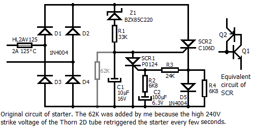
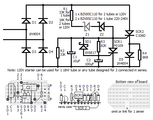
I assume you already know the tube must have an inductor (also known as a ballast) in series with it to stabilise the current. To avoid destroying your tube, short B & D together long enough for the filaments (cathodes) to heat and the ends to light up for a couple of seconds before removing the short across B & D to apply the high voltage, or connect a filament transformer to preheat them first. If the tube is allowed to start without the cathodes fully heated, the high voltage between the gas & the cathodes will cause the gas ions to blast atoms off the cathodes in a process known as sputtering (like sand blasting on an atomic scale) shortening tube life & blackening the ends. There is an English made starter in a green transparent case available from electronics wholesalers that fully preheats the cathodes(I think the brand is Pulse starter). I modified the circuit to suit available components. SCR1 in the original circuit was a PO124 specially selected for him by SGS Thompson to mimic the response time of a tube filament with changes in the supply voltage, and is not available in their datasheets. My cct. will give a roughly fixed time of about 3 sec. Adjust R3 if necessary to get at least 2.4 sec. Test it with a 100W incandescent lamp, assuming your supply voltage is about 240V (50W lamp for a 120V supply). If your supply is 120V, or you have 2 tubes in series, use 1 BZX85C110 zener and change R1 to 16K. The circuit was a brilliant bit of lateral thinking on the part of the designer using the Vbe on the gate of the SCR to top up C1, then R4 pulling down on the cathode, draining current back in from C1 during the zero crossing to retrigger it. Although fluorescent lamps are now absolete, UV lamps using the same technology are still used in laboratories, and for sterilisation etc.

enter image description here enter image description here

\$\endgroup\$
2
\$\begingroup\$

Yes it is the inductive surge that is created by the ballast when the switch suddenly opens. This surge creates a voltage spike that now appears at the cathode and anode and hopefully should create an arc wthin the tube. If no arc the cycle repeats itself as stated previously. The ballasts acts as transformer and choke. The choke part needed to create the arc and limit the current flow of the arc. The transformer portion needed to provide the proper voltage for the lamp and choke used. The longer the lamp the larger the choke?

\$\endgroup\$

Your Answer

By clicking “Post Your Answer”, you agree to our terms of service and acknowledge you have read our privacy policy.

Not the answer you're looking for? Browse other questions tagged or ask your own question.