This is my first time using a PID control loop so I have a lot to learn. I will explain what I am trying to do before I ask any questions.
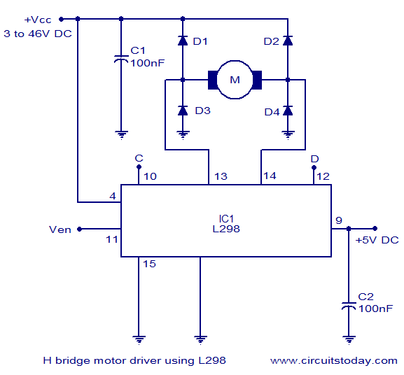
I have an FPGA running a processing core that I made myself, which works fine. I then have a 24Vdc motor (4500rpm rated) that is driven by a L298N H-bridge motor driver board. The FPGA provides the signals for run forward, run reverse and a PWM signal. Coupled directly to the motor is a 1000ppr 2 channel rotary quad encoder that measures rotational speed of the motor. There is a potentiometer that is used to set a speed setpoint for the motor, which is scaled to 0rpm to 4000rpm.
The FPGA is a Nexys A7-100T development board that has 2 four digit seven segment displays, and some latching switches. The goal of this system is for a user to set the speed setpoint of the motor which is displayed on one display, select motor run/stop and forward/reverse with the switches, and the FPGA should control the motor speed to match the setpoint. The motor measured speed is then displayed on the other seven segment display.
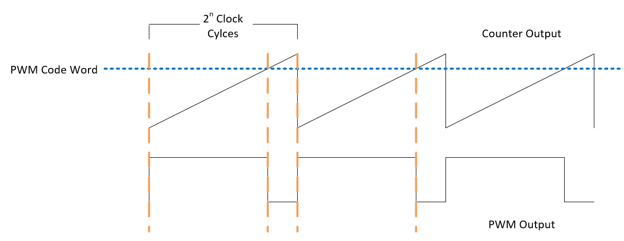
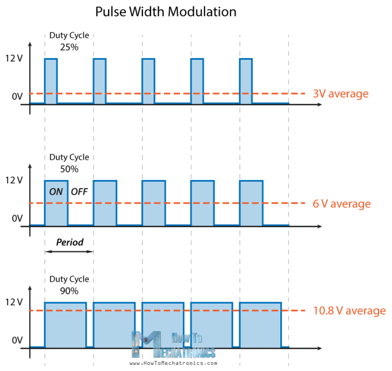
The FPGA clock is 100MHz and from that I generate a counter that counts from 0 to 5000 in a loop (I picked 5000 for a 20kHz PWM frequency). To generate the PWM signal, I compare a value that is calculated in the PID loop which will be between 0 and 5000. When the counter value is less than the comparison value, PWM signal is high and vice versa. I will post the PWM code at the bottom.
The PID code is performed every 24ms on the rising edge of a 41.67Hz clock. The speed setpoint and measured RPM are sampled in the processing program cyclically, which is around 2MHZ. But the calculated setpoints are performed by the PID code every 24ms. I am only proportional gain currently as I expect the system to just oscillate at worst. Then can add i and d.
My problem is that the motor keeps starting and stopping erratically, to the point where it starts, reaches 800rpm, and stops. The repeats this.
In the code below, bits 0 to 13 contain the setpoint speed and bits 14 to 27 contain the measured speed. Bit 28 is not used, bit 29 is run/stop, bit 30 is forward/reverse and bit 31 informs that the motor has stopped for changing direction. There is a FSM for this too but I didn't post as I think it is not the problem.
There are 3 processes in the code below.
-First is the counter
-Second is the PID code
-Third is for the PWM output switching
Now for my questions. I think everything mentioned above is ok, but I am happy to hear if anyone thinks this design may cause issues.
Does it matter that the PID output is updated every 24ms and fed into the counter when the counter is free running and not at 0?
Do I need to cap the PID output to a low threshold instead of 0? Say when the error is small like 10rpm, the PID output could be 20, which is a very small PWM duty cycle.
Could 24ms be too slow to refresh a motor control application?
What are your thoughts?
library IEEE;
use IEEE.STD_LOGIC_1164.ALL;
use IEEE.STD_LOGIC_ARITH.ALL;
use IEEE.STD_LOGIC_UNSIGNED.ALL;
use work.Data_Sizes_Package.ALL;

entity PWM_Counter_and_Comparator is

 Generic (Max_Counter_Value : integer := 5000);

 Port (PWM_Comparison_Value : in std_logic_vector(27 downto 0);
       Clock : in std_logic;
       PID_Clock : in std_logic;
       Run_Reset : in std_logic;
       PWM_Output : out std_logic
       );
end PWM_Counter_and_Comparator;

architecture Behavioral of PWM_Counter_and_Comparator is

signal Setpoint_RPM : integer range 0 to 5000 := 0;
signal Actual_RPM : integer range 0 to 5000 := 0;
signal Count_Value : integer range 0 to 5000 := 0;
signal PID_Comparison_Value : integer range 0 to 5000 := 0;
signal comp : integer range 0 to 5000 := 0;

constant Kp : integer := 2000;
constant Kd : integer := 0;
constant Ki : integer := 0;

begin

Setpoint_RPM <= conv_integer(unsigned(PWM_Comparison_Value(13 downto 0)));
Actual_RPM <= conv_integer(unsigned(PWM_Comparison_Value(27 downto 14)));

Process(Clock , Run_Reset)

begin

    if(Run_Reset = '0') then
      Count_Value <= 0;

    elsif(rising_edge(Clock)) then

         if(Count_Value = Max_Counter_Value) then
            Count_Value <= 0;

         elsif(Run_Reset = '1') then
               Count_Value <= Count_Value + 1;

         end if;

     end if;

end Process;


Process(PID_Clock , Run_Reset)

variable Error_RPM :  integer range -5000 to 5000 := 0;
variable Last_Error_RPM : integer range -500000 to 500000 := 0;
variable Error_Sum:  integer range -500000 to 500000 := 0;
variable Error_Change:  integer range -500000 to 500000 := 0;
variable PID_Output:  integer range -500000 to 500000 := 0;

begin

    if(Run_Reset = '0') then
      Error_RPM := 0;
      Last_Error_RPM := 0;
      Error_Sum := 0;
      Error_Change := 0;
      PID_Output := 0;

    elsif((rising_edge(PID_Clock)) and Run_Reset = '1') then

      Error_RPM := Setpoint_RPM - Actual_RPM;

      Error_Sum := Error_Sum + Error_RPM;

      if(Error_Sum > 50000) then
         Error_Sum := 50000;

      elsif(Error_Sum < -50000) then
         Error_Sum := -50000;
      end if;

      Error_Change := Error_RPM - Last_Error_RPM;

      PID_Output := ( (Kp * Error_RPM) + (Ki * Error_Sum) + (Kd * Error_Change) / 100);

      Last_Error_RPM := Error_RPM;

        if(PID_Output > Max_Counter_Value) then
            PID_Output := Max_Counter_Value;

         elsif(PID_Output < 0) then
           PID_Output := 0;

          end if;

      PID_Comparison_Value <= PID_Output;

      end if;

end Process;


Process(Clock , Run_Reset)

begin

    if((Count_Value < PID_Comparison_Value) and (Run_Reset = '1')) then
      PWM_Output <= '1';

    else
      PWM_Output <= '0';

    end if;

end Process;

end Behavioral;
EDIT 1
This image below shows the concept of generating the PWM using a counter and comparison value.
*Not my image, taken from Google images.
**EDIT 2 **
Here is a link to the L298N motor driver: L298N Motor Driver Board


