0
\$\begingroup\$

I'm working on a project where I need to control a MOSFET through an arduino uno. The MOSFET I've selected is a IRFP460, and the Vgs characteristic is Vgs = 10V.

Can I run it through an arduino PWM pin, even if its output only reaches 5V? What would be the negatives?

I've quickly tested it and it seems to work so far.

Thank you for any help!

Here's the MOSFET datasheet

\$\endgroup\$
2
  • \$\begingroup\$ Depends on the current you need to conduct. Check the datasheet for Vds @ Id for 5 V Vgs if it's listed. But then again, why make life difficult for yourself? Why not get a proper MOSFET for the task? \$\endgroup\$
    – winny
    Commented Apr 23, 2021 at 14:44
  • \$\begingroup\$ The maximum threshold voltage of this MOSFET is 4 V so that means when you make Vgs = 5 V that there is only 1 V "overdrive". That's not much especially if you want to switch the MOSFET fully on to switch a 10 A load for example. If you switch on/off a load that needs much less current then Vgs = 5 V could be OK. You do not mention what the load and how much current needs to be switched. The Vgs = 10 V is not a requirement but it is a test condition at which for example the on resistance is tested. I would use a MOSFET with a much lower threshold voltage designed for Vgs = 5 V \$\endgroup\$ Commented Apr 23, 2021 at 14:45

2 Answers 2

3
\$\begingroup\$

The problem with using the MOSFET under these conditions is that it is very unpredictable how much it will be turned on. The threshold voltage is specified as 4V maximum, however under those test conditions it is only guaranteed to conduct 250 microamperes, and that with 4V from drain to source, which is hardly turned on at all. Worse, that is specified at a die temperature of 25°C and it will be significantly worse at one of the temperature extremes (cold, in this case).

enter image description here

If your design only needs to operate at relatively warm conditions and you only need to switch 250uA maximum then there is probably plenty of margin and it might be considered a good design (other than using a part that's perhaps 100x more expensive and 10x bigger than it could be).

If you are switching more than a few hundred uA and really need to have guaranteed performance (so every item you produce works reliably) then you should operate the MOSFET in or at least near a region where the parameters are guaranteed. In this case, it's Vgs = 10V. A bit more than 10V is fine too.

In this case if you really need to switch such a high voltage you can use a gate driver circuit to get the required gate voltage (and to switch it quickly, so the MOSFET does not spend too much time in each switching operation dissipating hundreds of watts).

If you want to switch a lower voltage (like up to 20-30V), there are much more appropriate MOSFETs available, some of which are guaranteed with 4.5V, 3V or even 2.5V or lower Vgs (so-called logic-level MOSFETS). They also would likely have a much lower Rds(on) than the relatively high 0.27 ohms of this high voltage part.

For example, the very old IRLZ44 has a maximum Rds(on) about 10x lower when driven with 5V than your part has when driven with 10V, and will switch up to 60V.

Many newer parts are much better again.

\$\endgroup\$
3
  • \$\begingroup\$ Thanks for the response, it was very helpful! I'll try and explain better my setup to offer more information: I have a motor controlled both in velocity and in torque whose shaft is mechanically connected to a generator. The project requires me to connect the generator to a resistance through a MOSFET controlled by the arduino, so that according to the duty cycle imposed to the MOSFET, the generator will be connected to the resistance for a certain period, imposing a certain braking torque to the motor. The generator outputs over 400V according to the speed. continued \$\endgroup\$
    – Doche
    Commented Apr 24, 2021 at 18:28
  • \$\begingroup\$ Do you have any suggestion on how to better go about this situation? Could you give me an example of which gate driver circuit i'd need? Again thanks for the help! \$\endgroup\$
    – Doche
    Commented Apr 24, 2021 at 18:34
  • \$\begingroup\$ Yes, I could but I suggest you go to a distributor such as Digikey.com, look up gate drivers and compare datasheets. You can do a parametric search. You would want a "low side" gate driver. \$\endgroup\$ Commented Apr 24, 2021 at 20:52
1
\$\begingroup\$

In a typical MOSFET datasheet, you will find these two parameters (among other things):

enter image description here

enter image description here

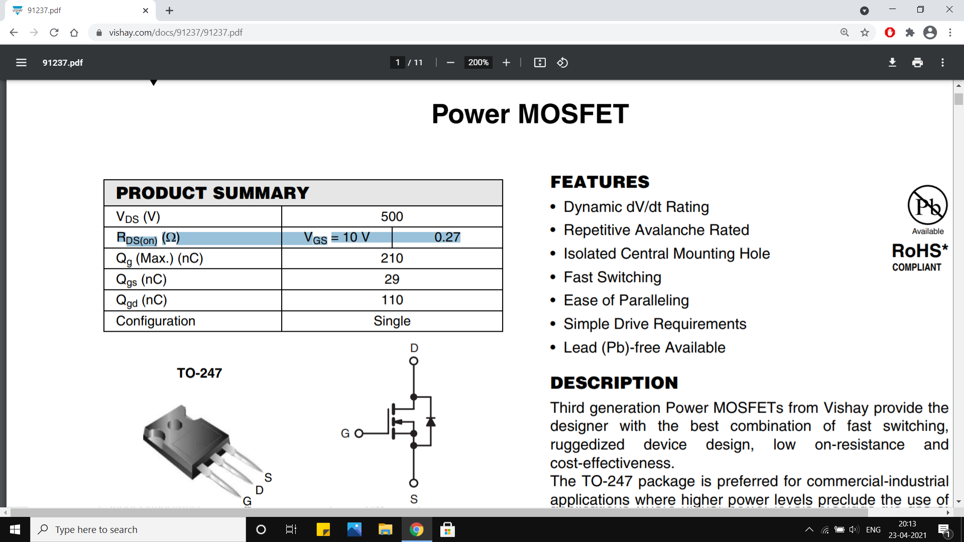
  • The data in the first screenshot tells you that the on resistance (aka Rds(on)) of the MOSFET for a gate-to-source voltage of 10V is 0.27ohms.

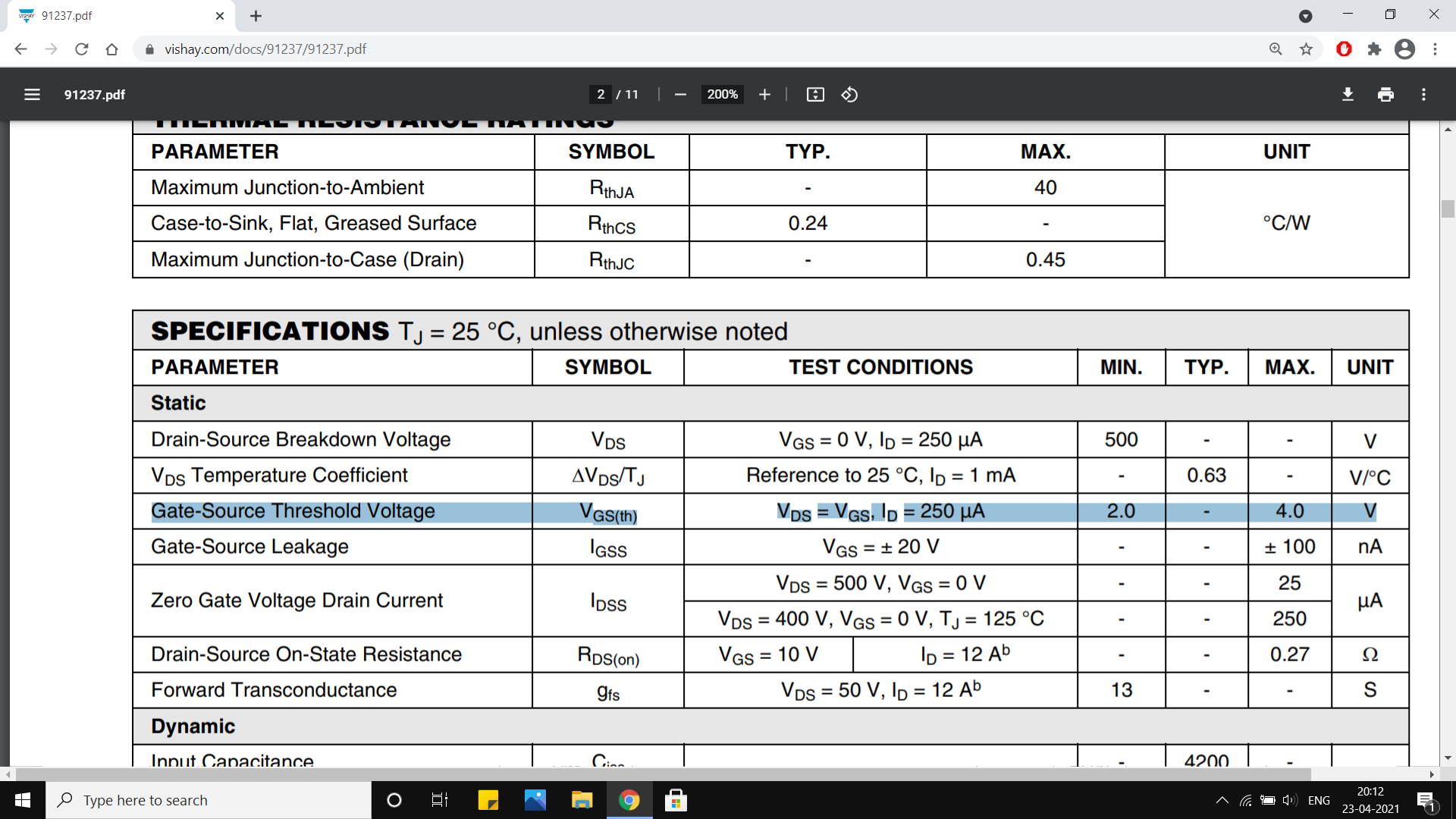
  • The data in the second screenshot tells you that the gate-to-source
    threshold voltage is anywhere between 2-4V.

Now let us understand the meaning of these data. The first tells you that the on-state resistance of the MOSFET is 0.27ohms when a Vgs of 10V is applied. This is typically the Vgs voltage at which the on-resistance of the MOSFET is determined. It does not mean that 10V is the GS threshold voltage.

The second data, on the other hand, does tell you what the Vgs threshold is. It says that the minimum Vgs(th) is 2V and the maximum Vgs(th) that you can expect is 4V. So if you are supplying 5V to the gate with respect to the source, then you are turning the MOSFET with a headroom of 1V worst case, which maybe ample. You can turn on pretty much any MOSFET fully with 5V Vgs and use it, but it's on state resistance for that Vgs may be a bit higher, say 0.3ohms or 0.35ohms for this MOSFET (or it could be higher). You can still control the MOSFET with a 5V signal.

If you want a guaranteed on resistance of 0.27ohms, then you should use a 10V or higher gate-drive signal. I generally drive my MOSFETs at 10V.

PS you also get logic level MOSFETs that guarantee the lowest Rds(on) at 5V.

\$\endgroup\$
3
  • \$\begingroup\$ Thank you for the response, it was insightful! The MOSFET is actually subject to upwards of 400V Vds, so I don't think such a small difference in its on state resistance would make a great difference, or am I misunderstanding? A lot of current will probably run through the MOSFET, in which case a correct and stable value of its resistance is fundamental for reliable results? \$\endgroup\$
    – Doche
    Commented Apr 24, 2021 at 18:40
  • \$\begingroup\$ The on resistance is not selected based on Vds, but it is based on Ids. If your mosfet is "subjected" to 400V and draws 1mA when it is on, you can use pretty much any 400V mosfet. But if your mosfet draws, say 3A, then you would need a low on resistance mosfet that is drive properly. And switching high currents at high voltages means you need to choose a fast mosfet and drive it with a powerful gate driver in order to minimise switching losses. There is actually a lot more to choosing and driving mosfets (espically at high voltages) that what i have said. \$\endgroup\$ Commented Apr 25, 2021 at 6:03
  • \$\begingroup\$ @Doche it seems that you are fairly new to this stuff, so i don't suggest that you play with high voltage. May I ask what you are trying to do? If you are new to MOSFETs and gate-drivers, it would seem that you dont have a lot of experience designing electronic circuits and I strongly advise you to stay away from high voltages. I suggest that you stick to the 0-32V range for your own safety. \$\endgroup\$ Commented Apr 25, 2021 at 6:08

Your Answer

By clicking “Post Your Answer”, you agree to our terms of service and acknowledge you have read our privacy policy.

Not the answer you're looking for? Browse other questions tagged or ask your own question.