I am asking for help with filtering input voltage for attiny2313. The schematics of the problematic board is here:
The circuit is powered by a MEAN WELL RD-125A power supply 5+12V.
There are 3 of these boards in the device each controlling one 12V 7 segment LED display.
This board is receiving data from a RPi and decoding it into a 7 segment output. The transistors are switching 12V 90mA each supplied by another output of the same power supply.
The problem we are experiencing is that random segments blink randomly when any other appliance for example a lamp is switched on/off while plugged in the same extension cord as the power supply. This is a problem for us because the device also has a relay and switches it's own 230V piezo siren causing the same blinking issue.
I think the problem is caused by poor input voltage filtering for the microcontroller. Unfortunately this is my first mcu project and I am kind of a noob. :D
I updated the schematic to this:
adding one more 1nF capacitor and an inductor into the power side of the attiny, I found similar arrangements in various datasheets.
Is this going to work? Are the values adequate?
Before you ask I know the LED resistors seem large, the LEDs use very little current, they all light up very well. :D
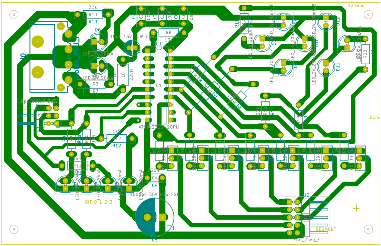
PCB Layouts:
This is the version that is currently having problems:

I have updated it to include the inductor and extra capacitor like this (this is not yet tested though):

The device also has separate board to which the mcu controller boards are connected:


The RPI connects to this board with the 40pin header which is split into 3 smaller connectors for 3 of the mcu controller boards. This board also has a USB connector at the top which provides power to the RPi.
All boards are connected to the same power supply and share the same ground through the Molex power connectors.
The weirdness you see around pins is because these boards are hand made and hand drilled and the extra copper helps with imprecise drilling.
The internal construction of the clock looks like this:

The two resistors on the heat sink up there are there because the Mean well power supply needs a minimal current draw. Mean well has two versions of the power supply with the same name. The new version does not need minimal current draw, the old version does need it. Unfortunately they only have the new datasheet on their website while shops still have the old version in stock.
The small board in the middle is the splitter which takes the RPI 40 pin connector and splits it into the individual mcu display controller boards. It also has the orange relay.
The siren is connected to the relay according to the layout above.
We tried shielding and grounding the signal cable which did not help.
 Thanks to the comments below we found that simply connecting the signal cable even with the other end not connected to anything causes the led blinking. The cable apparently works as an antenna and picks up enough interference to influence the inputs of the attiny. We wrapped the entire cable in copper tape and grounded it to the same ground which is connected to the RPi ground and all other ground pins. That did not stop the blinking. But it confirmed that power filtering is not the problem so we decided to use the software solution by requiring the input to keep the input value for a certain amount of time before showing it on the display.
If you need to know more information about the boards or PCB layouts feel free to ask.
Thanks.


