8
\$\begingroup\$

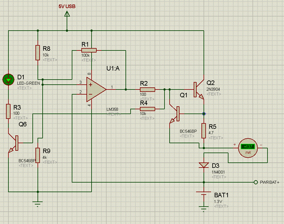
I've built a simple Ni-Cd charger (basically a 0.1C current source) for some 1300mAh cells, that I want to stop when a certain voltage is reached on the cell. I tried to design the switch with an Op Amp, but all it does is to limit the voltage the current source is applying on the cell, to the voltage that was supposed to trigger the cut off. I know I could use a relay, that would be driven by the Op Amp, but I'd rather really not use them.

So, how can cut off the power when a certain voltage is reached?

Here is a schematic of what I did, to give you an idea.

schematic

\$\endgroup\$
9
  • \$\begingroup\$ You want to cut off the power....until when? \$\endgroup\$
    – Phil Frost
    Commented Jan 27, 2013 at 14:52
  • \$\begingroup\$ I want to cut of power WHEN battery reaches 1.4V. \$\endgroup\$
    – Chris
    Commented Jan 27, 2013 at 16:19
  • \$\begingroup\$ right, cut it off, but when does it come back on? Is there a reset button or switch? When the voltage falls below some lower level (hysteresis)? \$\endgroup\$
    – Phil Frost
    Commented Jan 27, 2013 at 16:32
  • \$\begingroup\$ Exactly, as I mentioned in a comment bellow, it works in a hysteresis .. it cuts off the power when battery reaches 1.4V, and comes back on when battery drops to about 1.35V. The op amp is in a Schmitt trigger configuration. \$\endgroup\$
    – Chris
    Commented Jan 27, 2013 at 16:47
  • \$\begingroup\$ if that's what it's doing, I guess I'm not sure what the problem is, or what the question is asking. \$\endgroup\$
    – Phil Frost
    Commented Jan 27, 2013 at 17:04

4 Answers 4

6
\$\begingroup\$

You don't want to use fixed voltage charge termination for NiCd batteries. You do need to have some upper voltage limit as a safety, but charge termination is done with voltage slope and/or temperature.

NiCds exhibit a voltage "bump" when nearly fully charged with a reasonable current. The voltage actually goes down just a little. Therefore, look for the zero crossing of the voltage derivative, then add a little low current charge for a fixed time to top off the battery. For example, here is a full discharge and charge cycle of a 3-cell NiCd battery pack:

The battery is discharged to effectively empty at 3.4 hours. Until about 4.2h, a low charge current is used until the cells get to a sufficiently high voltage to be able to take "full" charge current. Note how the voltage goes up, exhibits a bump, and then goes down again at about 6.4h. The charge algorithm detects that by the zero crossing of the blue line and switches to low current top-off mode for a fixed 2 hours.

You are charging at a very low rate (.1C), so parts of this may not apply. It would be a good idea to measure a charge curve to see where you are at. Let it run long enough to know you fully charged the cell and see what both the voltage and derivative of the voltage look like. At such a slow charge rate, a fixed ending voltage may be the only choice, but it would be good to see the data before deciding that.

The way to measure and detect this is in a microcontroller. Each measurement will have some noise on it, but the signals are so slow that you can apply lots of low pass filtering. The signals are so slow that meaningful filtering in analog will be difficult due to the very high impedances required to realize them, and the result error caused by leakage currents. Digital values don't suffer from degradation over time, so you can do things like compute slope in volts/hour as I did for the blue line in the graph above.

\$\endgroup\$
1
  • 1
    \$\begingroup\$ I am aware of how Ni-Mh/Ni-Cd should be charged at high currents, but I only charge at 0.1C, and some manufactures specify that at this rate you don't even need a cut off trigger. But still, I would like to stop the charging at around 1.4V, which under 0.1C won't deviate much (I tested it). \$\endgroup\$
    – Chris
    Commented Jan 27, 2013 at 15:55
3
\$\begingroup\$

Your circuit looks like it should do exactly what you want it to
AND you say in your response to Chintalagirl that it does what you intend re cutoff voltage and hysteresis
SO I cannot understand what you want that you do not already have.

I recently implemented a commercial circuit for highish volume production using a circuit similar tothis one. It used a diode to allow low level voltage under hysteresis feedback to be set without altering trip voltage and used a TL431 to provide a more stable reference voltage - both as mentioned below.

V_USB cannot be reliably guaranteed to be 5V and may be higher or lower and may vary so a proper reference is needed. You can eg divide R8 into two parts and set the middle point at say 4V using eg a TL431 "programmable zener" / shunt regulator. These are cheap and effective in this role. Using a TLV431 allows 1.25V on up reference setting.

Better - you can set U1A pin3 AT the desired trip voltage with the TL431 BUT then the hysteresis feedback does not work so you can eg. Use a TL*V*431 with two resistors to set it to desired Vtrip.
Feed the TLV431 with about 1k to cathode from V_USB.
Feed TLV431 via say 10k to opamp non inverting input.
Use 100k or whatever hysteresis resistor as before with series diode. See below.

Using R1 as shown makes it hard to set high and low thresholds as desired as effectively R1 is in parallel with R8 before the battery reaches the trigger point and in parallel with R9 after the trigger point is reached so high and low set points are affected. Also, if the op amp does not swing to high rail fully it will affect the trip point calculation. Easier and just as effective is to place a diode in series with R1 so it conducts with only one opamp polarity so that either the high or low threshold is set only by R8 & R9. Best probably is to connect diode cathode to U1A output so that the diode conducts when the threshold has been reached and so then lowers the threshold when U1A output goes low. That way you can accurately set the desired trip point with R8 & R9 (which is what you most care about) and then R1 will lower this somewhat by an amount that you can calculate. The diode adds a small amount of complexity to the calculation of the lowered threshold but it is not very important as the main object is to terminate charging.

If R1 is too large the threshold will not be lowered enough and the battery voltage may "sag" enough after charge is removed to cause charging to restart. If you observe this with a meter and not with a scope you may think that you are seeing a stable DC voltage but really the circuit is oscillating. (Ask me how I know :-) ).

Inspection with an oscilloscope is always an extremely good idea with circuits like this as oscillation may easily occur.

It should not matter here but be aware that input common mode range for the LM358 is 1.5V below Vdd so here Vin max ~= 3.5.

Once you have added the diode suggested above you can test trip point by measuring at U1A pin 3. You can have R8 or R9 adjustable to set trip point. You can check correct operation by using a low leakage capacitor in place of the battery. This should charge to Vtrip and the circuit should then turn off and Vcap should equal target voltage. If the cap leaks you will see it recharge occasionally as Vcap falls below the lower threshold.

Q1 / R5 is a nasty way to do current setting as the Vbe reference is very imprecise - but it is good enough in this application. D3 is probably not strictly ncessary here but should do no harm. Without D3 Q1 and Q2 are potentially reverse biased by battery when the transistor is off but it should not be a problem here.

R1 hysteresis should stop this circuit settling into liner mode when setpoint is reached, especially with the diode added, but do check for oscillation. Usually adding a capacitor somewhere in either the drive or feedback loops will help. eg here U1A pin 3 might have a cap to ground BUT a better place would be pin 2, with the feed to pin 2 from the battery being via eg a 10k resistor. You can either express this in formal circuit theory pole/zero nomenclature or can see it as a delay in the rate at which the sensed battery voltage may change.

Ask as required ...
\$\endgroup\$
5
  • \$\begingroup\$ Thank you for all the info. I'm not worried about imprecise thresholds or currents, this won't go in mass production :). I am unhappy with my design because the charger does NOT cut off the current immediately when ~1.4V are reached on the battery, instead it is limiting the current source from applying more than 1.4V. So what really happens is that the cell is charged at ~130mA until it reaches 1.4V, and then very slowly, the current is dropped until the cell is 1.4V on it's own (with current source completely turned off).If I used a relay between opamp and current source,it would have worked \$\endgroup\$
    – Chris
    Commented Jan 27, 2013 at 17:54
  • \$\begingroup\$ @user1410908 - IF you work through ALL my comments you will see that I addressed what you are saying. If you try what I said and check each point it will probably work. Most likely are one or more of - Battery dropping enough to overcome hysteresis.- Operating in linear mode - OScillating. | All these are parts of the same thing. | IF you insert the diode that I suggested the opamp can never compensate with a positive correction signal - it can only lower the threshold or have no effect. This alone MAY help. | Have you checked with an oscilloscope for oscillation. \$\endgroup\$
    – Russell McMahon
    Commented Jan 27, 2013 at 21:31
  • \$\begingroup\$ @user1410908 - Also - the USB supply may rise as you deload it adding to feeback issues. Using a solid ref as I suggest gives you a stable level for the comparator to work at. | Try what I said systematically. It MAY work. \$\endgroup\$
    – Russell McMahon
    Commented Jan 27, 2013 at 21:32
  • \$\begingroup\$ I did work my way through all your comments, but I don't think the diode in series with R1 will make OA swing from rail-to-rail; in fact I made a simulation to test it out. Here is the result with comments postimage.org/image/eepazb6i3 . Did I get it wrong? \$\endgroup\$
    – Chris
    Commented Jan 27, 2013 at 23:19
  • \$\begingroup\$ USB voltage is stable (4.98); don't have an oscilloscope to check for oscillations but I don't think that's happening, besides simulation shows exactly what's happening in real circuit .. hope I don't look disrespectful, I'm not, I appreciate your help \$\endgroup\$
    – Chris
    Commented Jan 27, 2013 at 23:25
1
\$\begingroup\$

One solution, while possibly not ideal, could be to use a comparator or an op amp configured as a comparator. Have the negative input as your set voltage and positive as PWRBAT+. When the cell voltage crosses that threshold, the comparator output which was earlier floating will get pulled to ground. Connecting this output to the junction of R2 and R4 should turn off the transistor Q2 and render Q1 irrelevant and therefore halt the charging.

The set voltage can be generated using a simple resistor divider, since comparator inputs are high impedance.

The comparator should be able to sink as much current as is needed for the drop of the output opamp to 0 via the output resistor, which is probably fine for most typical comparators.

This method will have the advantage of being able to work with the circuit which you already have without too much modification.

\$\endgroup\$
4
  • \$\begingroup\$ If I put the negative input to my set voltage and the positive input to the battery,when the battery is below the set voltage, the output will be low, so it won't charge. I used instead set voltage to positive and battery to negative, but when battery gets close to set voltage, the output is slowly dropped so that the voltage applied at the battery (also the voltage at the negative input) by the current source is bellow set voltage.So the current is very slowly dropped until eventually gets to 0. I want it to stop suddenly when 1.4V are reached. \$\endgroup\$
    – Chris
    Commented Jan 27, 2013 at 16:18
  • \$\begingroup\$ I think that's what this circuit already does. The problem is, as soon as the voltage is below the set point at all, it comes back on. Naturally, once the current source is shut off, the voltage across the battery drops a bit. So really, it never shuts off; it reaches an equilibrium where the battery voltage plus the rise from the charging current is equal to the reference voltage. The OP needs to define under what conditions the current source is allowed to come back on. \$\endgroup\$
    – Phil Frost
    Commented Jan 27, 2013 at 16:36
  • \$\begingroup\$ The op amp is in a Schmitt trigger configuration (that's what the 100K resistor is for). If I force the voltage applied to the battery by the current source above the set voltage, AO output is immediately pulled to the ground, and won't start again until battery voltage drops bellow ~1.35V. It works in a hysteresis. \$\endgroup\$
    – Chris
    Commented Jan 27, 2013 at 16:44
  • \$\begingroup\$ I see the problem. My apologies. Perhaps bring the hysteresis level below the fall in the voltage when the supply cuts off? \$\endgroup\$ Commented Jan 27, 2013 at 16:56
0
\$\begingroup\$

I finally made it work. Russell, I tried adding that diode, but that didn't do the trick. I don't understand why you say that adding that diode would make the OA swing from Vcc to GND. The TL431, though, was a very good suggestion. After adding that relay(that draw 150mA), I needed a more reliable voltage reference than a supply voltage divider. Cheers for that! Anyway, I found at the local electronics shop a very small sealed 12V relay, that I had to brake it open, and adjust the coil to make it work with 5V. It was hell .. I ended up rewinding the hole coil by hand. But it was worth it, now it does exactly what I wanted it to do:

   - initial battery level is somewhere bellow 1.3V
   - USB is plugged in
   - battery is charged at ~150mA until the voltage applied by the current source is 1.49V
   - 1.49V is reached, the relay goes off, and the battery voltage drops to ~1.44V
   - charger won't start again until cell goes bellow 1.38V

Here is the final schematics: enter image description here

Thank you all for the help!

\$\endgroup\$

Your Answer

By clicking “Post Your Answer”, you agree to our terms of service and acknowledge you have read our privacy policy.

Not the answer you're looking for? Browse other questions tagged or ask your own question.